


N Cables & Adapters


Our N-Type Connectors' Corrosion Proof Materials Composition
- The materials composition of our Type-N connectors is oriented to ensure a durable, weatherproof connection
- Connector Body: Nickel-Plated Brass: The most corrosion-resistant of all plated brass alloys (better than gold-plated), for long-term outdoor exposure.
- Our standard nickel-plated N-type connectors can resist 70 hours salt spray test without any corrosion-defect.
- For corrosion-resistance of 120 hours in a salt spray test: We have to customize the connector. No tooling cost, but it adds an additional 4 weeks delivery time and the product cost will be 20% higher than the standard cable assembly.
- Center Contact: Beryllium Copper, Gold Plated
- Crimp Ferrule: Copper, Nickel Plate
- Insulators: PTFE
- The N-male and N-female connectors have an internal rubber O-ring. When mated to an N-type connector of the opposite gender with a rubber o-ring (at an enclosure port) it provides a water-tight seal rated IP-67 (based on use with Data Alliance’s N-female connectors with a rubber o-ring).
Frequency Bands & Electrical Characteristics
- Our N-type antenna cables' rated range of frequency band compatibility is from 900GHz to 6GHz)
- Impedance Matching: 50 Ohms
- Capacitance: Approximately 24.5 pF/ft (80.3 pF/m)
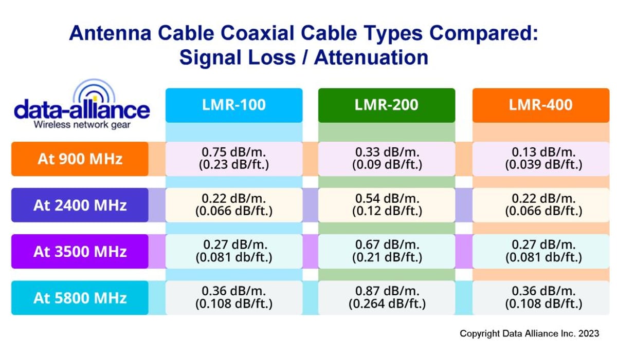
- Attenuation (signal loss):
- At 900 MHz: 0.33 dB/m. (0.09 dB/ft.)
- At 2400 MHz: LMR-200 = 0.54 dB/m. (0.12 dB/ft.)
- At 3500 MHz: LMR-200 = 0.67 dB/m. (0.21 dB/ft.)
- At 5800 MHz: LMR-200: 0.87 dB/m. (0.264 dB/ft.)
Compatibility with Wireless Standards & Applications
- Our N-type antenna cables are compatible with all WiFi standards: Wi-Fi HaLow 802.11AH, 2.4GHz or 8GHz applications: Wi-Fi 6, WiFi 6E, 802.11AX, 802.11AX, 802.11AC, and earlier Wi-Fi standards: 802.11N, G and B.
- Cellular Wireless LTE / 4G, LTEm, GSM / 3G, 5G, WiMax
- IOT (Internet of Things) wireless protocols: Bluetooth, ZigBee, LoRa, M2M, RFID, NB-IoT.
N-Type Connector Dimensions & Other Characteristics
- N-male inside diameter is 0.620-inch (1.57 cm) and N-female is the same.
- N-connector gender is counter-intuitive: Click here for details. Gender refers to the pin inside and not the threads.
- N-Type connector is the largest of the RF connector types, and are usually found on large antennas, especially for outdoor use.
- Our N-Type connectors feature threaded coupling mechanisms and are fully interchangeable with N-Type connectors made to the MIL-C-39012 specification. These connectors are used in all systems where excellent RF and mechanical performance is critical.
- Our N-male connectors are knurled, so that they can be tightened by hand.
N-Type Cables to All Antenna Connector Types
- Data Alliance provides N-type cables with LMR-100, LMR200, and LMR400 type coax as well as 1.13 for use with U.FL and MHF4 cables: These coaxial cables are designed to provide distortion free signals.
- Offers bandwidths up to 11 GHz.
- Our N-connectors (including the nuts and washers that come standard on our N-female connectors) are nickel plated and therefore are rust proof.
- Available in right angled models that facilitate their use at cramped locations in order to let the WiFi antennas remain vertical
- Available in threaded and slip on versions
- All of Data Alliance's N-type cables and adapters are 50 Ohms impedance
N-Type Connectors: Characteristics, Specifications, Applications
N-type connectors have a rugged dependability and durability even in harsh conditions. Type N connectors, when properly mated will couple and seal (using an O-ring) to a rating of IP67. At IP67 the contact is free from solid contaminants such as dust and sand, waterproof to a significant depth of immersion, and is vibration resistant. They are therefore weatherproof and suitable for outdoor applications.
N-connectors are medium-sized threaded connectors that are used in a variety of cable assemblies. They are one of the most commonly used radio frequency connectors in circulation. Type N connectors are available in 50 and 75 Ohm versions that are not intercompatible due to marked structural differences. They are also known as:
- Navy connectors
- N-Type connectors
- Type N connectors
Type N is a medium-sized RF connector with threaded coupling used to in antenna cable assemblies. The male and female connectors are usually made of nickel-plated brass (some are made with stainless steel). They terminate to either a coaxial cable or to a circuit board by crimping, clamping or soldering. The male and female are fully interchangeable and mostly comply with MIL-C_39012 specifications.
Type-N connectors are designed for medium to high power applications and can handle frequencies up to 11 GHz (standard designs) and 18 GHz for precision designs. These connectors are used in various applications, including military, satellite, and broadcast systems, due to their robust design and capability to handle significant power levels.
The N connector can be paired with coaxial cable that is flexible, semi-rigid, or helical with corrugated copper for a wide range of applications. These rugged brass or stainless steel connectors are widely used in telecom and wireless networking applications that require good power handling and weatherproof connection. N connectors can also be mounted on panels or printed circuit boards by crimping, clamping, or soldering.
Physical specifications of the N connector
N connectors are threaded male and female connectors that mate by screw coupling. They are made from nickel-plated brass or stainless steel. They carry 5/8 - 24 pitched UNEF threading. As a medium-sized radio frequency connector, the N connector is larger than subminiature threaded radio frequency connectors like the SMA or TNC connectors. The specifications for N connectors include:
- CECC22210
- MIL-PRF-39012 (MIL-STD-348B)
- IEC 61169-16 standardization.
When properly mated, N connectors form a watertight and weatherproof connection that is rated for over 500 mating cycles. The addition of an O-ring seal to the mated connection achieves an IP 67 rating. This means that the connection is free from solid contaminants such as dust and sand, waterproof to a significant depth of immersion, and vibration resistant.
Standard N connectors do not have a dielectric but precision N connectors may carry a small amount of PTFE (Teflon) insulator material within them.
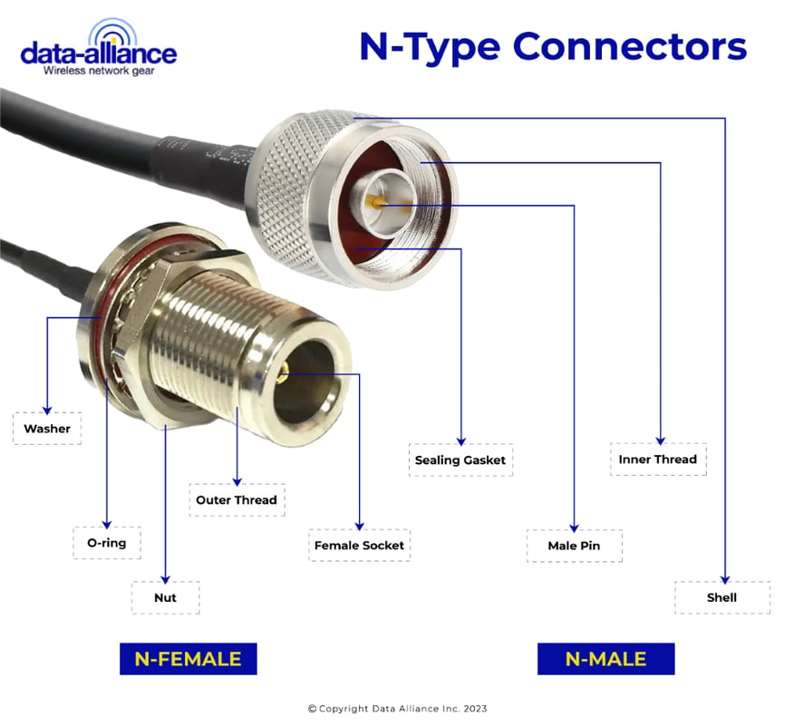
Male N connector
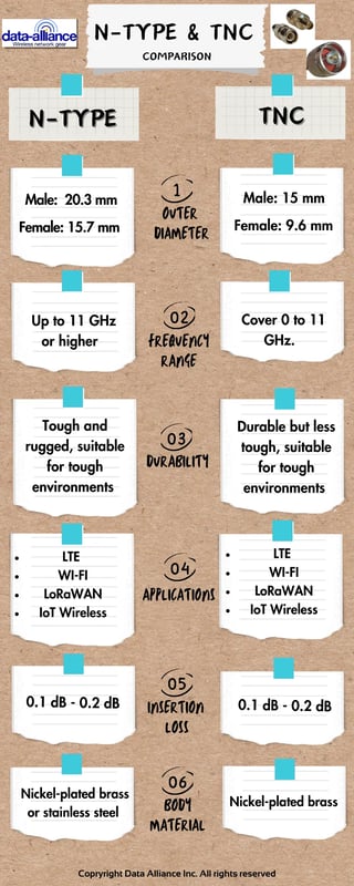
The male N connector has a diameter of 0.800 inches (20.3 millimeters) with internalized threads. It carries a hex nut that can be tightened with appropriate torque wrench. The mating interface of the male Type N connector has a brass pin as its center conductor.
Female N connector
The female N connectors have external threading on the connector body. The outer diameter of the female N connector is 0.620 inches (15.7 millimeters). The female N connector carries a beryllium copper receptacle that receives the male pin when it is fully mated by the male connector screwing down and over it.

N connector electrical specifications
- Standard N connectors have an impedance of 50 ohms. There are 75-ohm versions, but they are functionally incompatible with the 50-ohm N connector and can damage the standard N connectors if mated incorrectly.
- Type N connectors support frequencies up to 11 GHz. Precision versions of the N connector have a frequency limit of 18 GHz.
- Type N connectors have a peak voltage rating of 1500 volts and a dielectric withstanding voltage of up to 2500 volts. The superior power handling makes it a radio frequency connector of choice for high voltage devices like surge protectors. It is often selected in preference to BNC or TNC connectors for a variety of high voltage applications.
- N connectors have a VSWR of 1.3.
- The contact resistance is 1 milliohm with an insertion loss of 0.15 dB.
- Radio frequency leakage of the Type N connector is -90 decibels at 3GHz.
Applications of N-type connectors and N-type cables
Type N connectors are designed for use in systems where reliable RF and performance is important. They were initially used by the military for Microwave transmission. Since then there has been a wide variety of applications, due to their durability, and the introduction of right-angled connectors for convenient cable management. Type N connectors are used in a wide range of applications from low- frequency to high-frequency equipment. Here are some of the areas the Type N connector and cables are widely used:
- Broadcast systems
- Base stations
- Microwave Radio
- Outdoor antennas
- Radar equipment
- Satellite systems
- Surge protection
- Wireless LAN
Type N connector history
The N connector is one of the earliest microwave radio frequency connectors. It was invented by Paul Neill of Bell Labs in the 1940s as a key military microwave connector for the US Navy Bureau of Ships. The first N connectors were capable of supporting frequencies up to 1 GHz, subsequent refinements to the design has raised its maximum frequency to 11 GHz. The “N” in N connector was thought to stand for “Navy”, but actually refers to the initials of its inventor, Paul Neill.
Applications for the N connector have expanded from its military origins to include diverse civilian and communications infrastructure applications where its ruggedness and suitability to outdoor use is advantageous. Later modifications including adjustments of the dielectric in the connector by Hewlett-Packard and other electronics companies led to the modifications that set the current electronic specifications of this RF connector.
There are two versions of Type N connectors. 11 GHZ at 50 Ohms impedance, and 3 GHz at 75 Ohms impedance. Both have different applications and should not be interchanged. Mating parties of different versions may result in permanent damage to connectors. [All of Data Alliance's N-type cables and adapters are 50 Ohms impedance].
The only issue with the connectors is sometimes distinguishing the 50 Ohm and 75 Ohm connectors. Some manufacturers don’t usually label them, unaware individuals may force a coupling of the different versions causing a loose and unreliable connection or permanent damage.