


- Antennas: Our Products Subcategories
- How To Choose WiFi Antenna
- Range & Radiation Patterns
- Omni-Directional Applications & Patterns
- dBi dB, dBm dB(mW) Defined
- dBi Multiplier: Signal Power
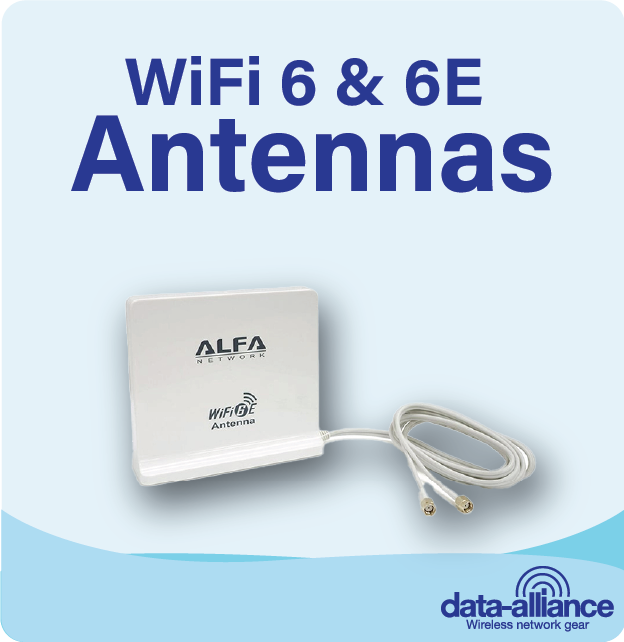
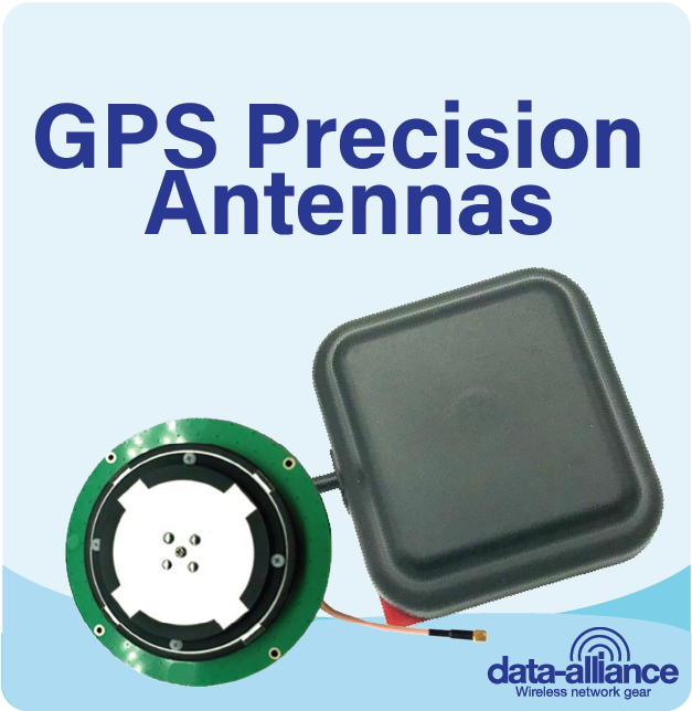
Antennas


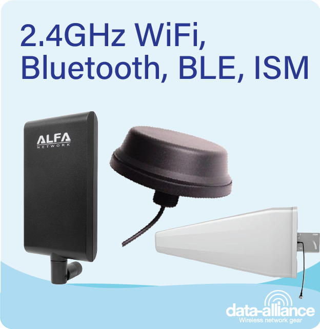


Omni-Directional Antennas Applications, Radiation Patterns & Range
- Bigger is not always better: Optimal choice of dipole antenna is determined by the relative positions of the access point and the clients, and range.
- Omni-directional antennas pickup stray "interference" signals that can degrade performance. To send/receive a signal in a particular direction, use a directional antenna.
- 2dbi - Best if relative-positioning is on different elevations: Such as different floors of a building.
- 5dbi - If you wish to send your signal over a couple of levels of a building, a 5dbi dipole is more recommendable.
- 7dbi - Optimal balance between range and elevation
- 9dbi - Best if distance is long and AP and client are on the same elevation (horizontal plane)
ABOVE: A 9dB antenna can be seen at 4-5 times the distance of the 2dB antenna but it can only be seen within 5 feet of its horizontal beam path.
Think of the wireless radiation pattern as a fat donut with the antenna sticking through the middle of the donut. As the gain of the antenna is increased the fat donut starts to flatten out significantly to the point where you will have a donut so flat it will resemble a CD disk: Round but very flat and anything above it or below its path won't see it.
At right: Radiation pattern of the 2dB omnidirectional antenna at right (bottom pattern in image)
-
A low gain (2dB) omnidirectional antenna like this provides a strong signal in every direction
-
Intended for short range meshed networks and reaches everyone within its range.
-
If you are in a building and need to cover the rooms around you then you are better off with a 2dbi dipole antenna, as they make sure you cover everyone equally in all directions
Diagram below shows the radiation pattern of a 2dBi omni-directional dipole antenna (vertically polarized):
This diagram shows the relationship between the E and H planes for a vertically polarized omni-directional dipole antenna. This is the type used in wireless repeater systems and it is intended for short range meshed networks and reaches everyone within its range.
Polarization of the wireless antenna is the orientation of the wireless signal. It can be vertical, horizontal, circular or combinations of these.
The E-plane and H-plane are reference planes for linearly polarized antenna.
Range & Radiation Patterns of Antennas
| Radio waves do not penetrate obstacles very well. High-gain antennas have a flat radiation pattern: So, a larger antenna will only help for long range; it will not help if you have differing elevations. Use high power antennas to send a signal long distances to a very specific and focused point. The higher the gain, flatter the signal radiation pattern.Low power antennas send their signals to higher and lower elevations in local area: Everywhere within their 100-200 foot range.
|
|||||||||||||||||||||
|
Antennas generally have greater coverage at the expense of range, and greater range at the expense of width of coverage area ("half-power beam width"). Therefore, omni-directional antennas, which radiate the beam in all directions (on a horizontal plane) generally have gains no higher than 12dBi, while directional antennas can have gains up to 30dBi. As a general rule of thumb: The higher the gain, the narrower the beam width (coverage area). Half-power beam width is the specification of the antenna's coverage area. It is measured relative to the points at which the antenna's radiation drops to half its peak value.
INDOORS / BUILDINGS See also this page on dipole antennas. Metal reflects the signal. Modern houses may also have foil backed plasterboard to meet fire regulations and modern glass has a metal content. This said, as a general rule 802.11g/ WiFi devices will cover a house quite well, not guaranteed though. Bear in mind if your WiFi antenna is placed down behind the computer case it already has two layers of steel and a wall to penetrate first. Indoors coverage: We recommend using the low power 2dB antennas and using more wireless repeaters spaced every 100 feet to properly cover an area. Laptops only transmit 100 feet so there is nothing gained by having a high gain antenna on one end when the laptop can't even talk back more than 100 feet. Making sure that all repeaters are no more than 100 feet from each other ensures that laptops can always see a repeater or two. |
dBi dB, dBm dB(mW): Defined & explained
dBi dB(isotropic): The forward gain of an antenna compared with the hypothetical isotropic antenna, which uniformly distributes energy in all directions. Linear polarization of the EM field is assumed unless noted otherwise.dBm dB(mW): Power relative to 1 milliwatt. When used in audio work the milliwatt is referenced to a 600 ohm load, with the resultant voltage being 0.775 volts. When used in the 2-way radio field, the dB is referenced to a 50 ohm load, with the resultant voltage being 0.224 volts. There are times when spec sheets may show the voltage & power level e.g. -120 dBm = 0.224 microvolts.
"dBm" is used to compare against watts. There is no direct correlation between watts and dBi. dbm is logarithmic and mw is linear.
The term "dB" is not a reference but is rather a method and a measurement standard. dB must be used against a standard, hence "dBm" is used to compare against watts.
WiFi Antennas: How To Choose / Application Examples
The two main categories of WiFi antennas are omni directional and directional.Omni directional antennas provide 360 degree coverage in a donut shaped radiation pattern: Providing the widest possible signal coverage for indoor and outdoor wireless applications: Types of omni directional antennas include dipole ("rubber duck") antennas that come as the default antenna on access points and routers, omni antennas found outdoors, and antenna arrays used on cellular towers.
For WiFi inside an office building To provide wireless coverage to an inside office space, use omni directional antennas that provide 360 degree wireless coverage. The style of antenna typically used is the ceiling mount omni directional antenna. The antenna gain pattern for the ceiling mount Omni directional antenna in this application is donut shaped with good vertical and well as horizontal coverage providing connectivity to WiFi devices including laptops, printers, tablets, and smart phones.

How to install WiFi in a campus environment (outside) In this case you can use several directional antennas with an omni directional antenna at the central building to connect the building in the campus. This is called a point to multipoint network. As with any outdoor Wifi network, clear Line of Site is critical. Additionally, proper antenna alignment is necessary to ensure optimal signal quality.

Connect one building to another building In this design scenario you will need a directional antennas such as Yagi, or parabolic grid antennas. This is called a point to point wireless link. Each building should be outfitted with a directional antenna and the antennas need to point at each other inline. Also make sure there are no obstructions between the two antennas such as trees or buildings. Clear Line of Sight is critical.

Provide WiFi access in an outdoor cafe For an outdoor cafe use Omni directional antennas to provide 360 degree signal coverage to customers and employees. Try and mount the antenna as close to the center of the WiFi coverage area as possible. Also remember that if the Omni antenna you use has too much gain, then the users beyond the cafe area will tend to get better signal then those within the cafe area. Using a lower gain (dBi) antenna will result in more of a doughnut shaped signal pattern which gives better vertical coverage bringing the signal close to the ground where patrons are sitting with their WiFi devices.

Increase in dB of antenna results in power increase multiplier-effect
|
net dB added (after cable loss) 3.0 dB 3.5 dB 4.0 dB 4.5 dB 5.0 dB 5.5 dB 6.0 dB 6.5 dB 7.0 dB 7.5 dB 8.0 dB 8.5 dB 9.0 dB 9.5 dB 10 dB 12 dB 13 dB 16 dB 19 dB 20 dB 30 dB 40 dB 50 dB 60 dB |
Increase in power: Multiple 2.0X 2.6X 3.2X 3.8X 4.3X 4.9X 5.5X 6.0X 6.6X 7.2X 7.7X 8.3X 8.9X 9.4X 10X 15X 20X 40X 80X 90X 500X 10,000X 100,000X 1,000,000X |