


Antennas By Connector Type


Antenna Connectors: Applications & Characteristics
An antenna connector is a radio frequency connector located at the termination of an antenna. Its attachment to the antenna provides a conduit for the transmission of radio frequency signals, keeping signal loss, discontinuity, and impedance mismatches to a strict minimum. An antenna connector should maintain the electrical conditions for the transmitted current to travel under shielded conditions to an attached antenna cable, circuit board, or radio.
The connection provided by the connector at the base of an antenna provides an electrical connection and a mechanical one. In many antennas, the connector is the single point at which the antenna is secured to the radio frequency device or assembly and needs to be capable of withstanding mechanical stresses. They also may undergo frequent mating cycles with a complementary coaxial connector on cables, power amplifiers, adapters, or PCBs. There is a wide range of antenna connectors, which vary by physical and electrical profile. Certain types of connectors are suited for particular antennas and applications, and the key types of antenna connectors discussed in this article are closely associated with specific applications.
Why are antenna connectors important?
Though connectors should be passive components in an antenna assembly, antenna connectors remain critical for maintaining the connection chain within a functional radio frequency circuit. The quality and integrity of the connection maintained by an antenna connector will often underpin the operation of a wireless device. Poorly selected, applied, and connected antennas will impair the performance of a radio frequency system and mean that the antenna will not appear to function as specified with loss of connectivity and data.
The mechanical and structural properties of antenna connectors are important, too. Depending on how the antenna is mounted, a connector may be part of a hinged, rotating, or recessed arrangement within the antenna. The size and caliber of an antenna connector determine how the antenna will be embedded in or installed on a device, which is important if space is a concern. Mechanical failure or the inability to mount the antenna properly will also render the whole unit inoperable.
Key Classes of Antenna Connectors:
[A] Antennas with SMA connector
Description
This is a miniature, semi-precision threaded connector that is widely used as a reliable termination for antennas of varying frequency. It is manufactured with a high degree of accuracy. The initials SMA stand for Sub-Miniature type A, a designation acquired in the late 1960s after its development as a novel miniature connector with military specifications.
Antennas can be terminated with either a male or female SMA connector which mate by the male screwing down onto the female counterpart and being tightened via a hex nut. This provides a stationary and durable connection between an SMA antenna and its attached cable.
Physical specifications of the SMA antenna connector
The military standard MIL-STD-348 specifies the physical characteristics of the SMA connector, which are maintained in contemporary generic versions. This threaded connector has a ¼ inch-diameter barrel with 36 threads per inch. SMA connectors have two complementary components:
- A male connector that has a 5/16 inch hex nut for tightening its internalized threads and a connector pin within its mating interface.
- A female connector with externalized threads and a mating interface containing a receptacle.
The body and coupling nose of the SMA connector are usually made from stainless steel or brass. The inner contacts are made from brass or copper and surrounded by a PTFE (Teflon) insulator. Some SMA connectors carry a silicone rubber gasket for additional weatherproofing. When properly connected, the SMA connector is rated for 500 mating cycles.
SMA connector electrical specs
- Frequency range: The SMA antenna connector supports reliable broadband performance with low reflection, from DC to up to 18 GHz, depending on its specific fabrication.
- Impedance: 50 Ohms.
- Voltage rating: SMA connectors can tolerate a peak voltage of up to 500 volts, depending on the antenna or cable to which it is attached.
- Voltage Standing Wave Ratio: VSWR is 1.15 + 0.1f (depending on the frequency at which the connector is used).
- Radiofrequency leakage: -90dB per minute at frequencies between 2 and 3 GHz.
Key applications
In recent decades, the SMA connector has been favored as a connector of choice for wireless systems and devices. It partners well with semi-rigid and flexible coax antenna cables, and PCB-mountable jacks are available to connect SMA antennas to circuit boards. Its small size, robustness, and consistent performance at UHF / microwave frequencies mean that it is widely used in cellular networking and is usually the connector provided with cellular antennas. It can tolerate outdoor waterproofing conditions, and when properly torqued with an SMA connector wrench, the connection it forms is weatherproof. It is also used widely in GPS antennas and devices. The rapid expansion of consumer wireless networking, particularly WiFi, has also led to using SMA connectors in some WiFi antennas.
[B] Antennas with RP-SMA connector
Description
The RP-SMA connector found at the base of many antennas is simply a variant of the standard SMA connector. The RP-SMA connector looks identical to an SMA connector and has a similar mechanical and electrical performance to its standard counterpart. The key difference is the reversal of the gendered inner mating interfaces of the connector, which means the designation of reversed polarity (RP) is given. RP-SMA connectors were designed in the 1990s, concurrent with the rise of consumer wireless devices. The US Federal Communications Commission was concerned that the widespread availability of SMA connector antennas would make it possible for high-gain antennas to be illegally connected to consumer devices. Production of a reversed gender connector, as described below, meant that though the connector looked like an SMA connector, it could not form an electrical connection with SMA connectors. By doing this, consumer and professional-grade products were effectively separated. However, the RP-SMA connector has become as ubiquitous as the SMA connector.
Physical features of the RP-SMA antenna connector
Like the SMA connector, the RP-SMA antenna connector is a threaded connector that mates by screw coupling. The connectors carry 36 threads-per-inch threading and are tightened via a hex nut. They are made using similar materials and fabrication methods to the standard SMA connector and come in a similar range of orientations, including bulkhead and PCB-mountable versions.
- Male Reverse-Polarity SMA connectors have internalized threads, a hex nut, and an inner socket rather than the center pin carried by a male SMA connector. The gender of the inner mating interface is switched.
- Female Reverse Polarity SMA connectors are still a barrel with externalized threads but carry a center pin rather than a socket.
It is important to carefully check the connector that an antenna carries to determine if it is RP-SMA (male: internal threads with a receptacle/socket) or SMA (male: internal threads with a center pin).
Electrical
RP-SMA antenna connectors are 50-ohm connectors typically used in wireless applications operating at gigahertz frequencies. Like the SMA connector, they can reliably support frequencies up to 18 GHz. As discussed above, their electrical performance is the same as that of the SMA connectors.
Key applications
The primary of the RP-SMA connector on antennas is to prevent the use of professional-grade high-gain antennas on consumer equipment. They are usually found on WiFi antennas and associated hardware. However, care must still be taken to ensure that SMA connectors are not used concurrently (e.g., if GPS or cellular functionality is also present in a device). Therefore, RP-SMA connectors are widespread in consumer wireless networking equipment and devices. This means that where an antenna can be disconnected, the RP-SMA antenna of choice can usually be easily installed as a replacement.
[C] N-type connector
Description
The N-type connector was developed by Paul Neill, an electrical engineer, in the 1940s. It is efficacious as a larger, hard-wearing connector type for microwave radio frequency transmissions in various external conditions. The contemporary version is more widely known as Type N and is usually fully interchangeable with the original.
Over the decades, this threaded connector has proven durable in design and performance for antennas and radio frequency circuits operating at 50 and 75 Ohm. It is useful as it accommodates a range of coaxial cable diameters.
N-type connector physical specs
MIL-STD-348 outlines the specifications of this antenna connector. The N-type connector consists of an inner pin or socket that serves as the center conductor which is surrounded by an air gap, separating the center and outer conductors. They are usually made from brass with gold or silver plating on the inner contacts. Some versions carry a rubber gasket for weatherproofing.
- The N-male connector carries a center pin and internalized threads.
- The N-female connector has an inner receptacle into which the male pin is inserted for an electrical connection. Its threads are externalized.
The barrel of the male N-type connector permits hand tightening, though some connectors carry a hex nut. Mating is via the connector's 5/8-24 threaded coupling and is rated for up to 500 mating cycles. Mismatching between 50 and 75 Ohm variants can damage the connector.
Electrical specifications of the N-type connector
- Frequency range: Type N connectors have a frequency range of DC to 11 GHz.
- Impedance: 50 Ohms or 75 Ohms (a slight structural difference exists between the 50 Ohm and 75 Ohm versions).
- Voltage rating: The peak voltage of the contemporary N-type connector is 1500 volts.
- Voltage Standing Wave Ratio: VSWR is 1.3
- Radiofrequency leakage: -90dB per minute.
Key applications
The Type N connector is used on various antennas in settings ranging from base stations and satellite systems to industrial environments and testing and measurement. It is often used for antenna connections, which require ruggedness, the ability to withstand vibrations, and repeated manual connection and disconnection. In recent times, this connector has been used for wireless networking, as certain versions can support frequencies of up to 18 GHz.
[D] MMCX connector
Description
The Micro-Miniature CoaXial connector is a miniaturized snap-on connector that permits 360-degree connection rotation. They were developed in the late 1990s as a 35% smaller version of the Swiss-designed MCX (Micro Coaxial) connector. The CECC 22220 specification manufactures them. They are remarkably robust and rated for 500 mating cycles, which is exceptional for a size connector. As they are designed to be embedded on PCBs, the force necessary to engage this connector is carefully calibrated to prevent damage to the solder and surrounding connections.
Physical specs for the MMCX connector
MMCX connectors are usually made from brass and have gold or copper-plated inner contacts. The center pin (male) and socket (female) are surrounded by a PTFE dielectric.
Electrical specifications of the MMCX connector
- Frequency range: This class of connectors supports frequencies from DC to 6 GHz, making it suitable for applications requiring reliable broadband performance.
- Impedance: 50 Ohms.
- Voltage rating: 170 volts.
- Voltage Standing Wave Ratio: VSWR is 1.25
- Radiofrequency leakage: -60dB per minute.
Key applications
The MMCX size and ease of mating provide an advantage for introducing wireless connectivity to various devices. MMCX connectors are used in WiFi, PCS, GPS, and other forms of wireless communication. They are especially beneficial in applications where space and weight allowances are restricted. They can fit onto densely populated circuit boards and deliver robust performance, so they are often used with internal antennas.
[E] TNC connector antennas
Description
The Threaded Neill Concelman connector is a threaded variant of the Bayonet Neill Concelman (BNC) connector developed in the 1950s. Its secure screw coupling means that it exceeds the BNC connector in supporting microwave frequencies.
Physical features of the TNC connector
The TNC connector structure is fabricated in line with MIL-C-39012 specifications and has a diameter of just over half an inch. It is typically made from brass with a beryl copper receptacle on the female connector and a brass center pin on the male. The insulator is made from PTFE. Male and female connectors carry 7/16-28 threads, externalized on the female and internalized on the male. When properly mated and tightened via hex nuts, if present, they form a robust connection that can withstand shocks and vibrations. A silicon rubber gasket also provides additional waterproofing in some versions. It is rated for 500 mating cycles.
Electrical profile of the TNC connector
- Frequency range: The TNC connector supports radio frequency transmissions up to 11 GHz.
- Impedance: TNC connectors come in 50- or 75-ohm designs. Most commercially available TNC antennas are fitted with the 50-ohm connector.
- Voltage rating: 500 volts.
- Voltage Standing Wave Ratio: VSWR is 1.35
- Radiofrequency leakage: -55 to -60dB per minute, depending on impedance.
Key applications of TNC connectors
This medium-sized connector provides secure mating for wireless networking solutions and instrumentation. It can also terminate a wide range of coaxial cable types.
[F] Antennas with RP-TNC connector
Description
The Reverse Polarity TNC is functionally identical to the TNC connector but has a reversal of gender of the inner central conductors. This means that though an RP TNC connector looks like a TNC connector, it cannot form an electrical connection with it. Both TNC and RP TNC antenna connectors should be carefully examined to ensure they are correctly paired.
Physical characteristics
Like the TNC connector, the TNC connector is a brass 7/16-28 threaded connector with a center conducting element surrounded by a PTFE insulator. The male RP-TNC connector has internalized threads, but it is a receptacle instead of the standard pin. The externally threaded female connector carries the center pin. This means that the gender of the inner conductor is reversed. The connector mates by screw coupling and is rated for 500 mating cycles.
Electrical specifications
RP-TNC connectors have comparable electrical performance to their standard counterparts discussed above. They are available with a 50-Ohm impedance.
Key applications of RP-TNC connectors
The reverse-polarity TNC connector was developed in the late 1990s for use on consumer wireless products. The purpose of using this version of the connector was to curb the opportunity for amateur attachment of professional-grade TNC antennas and equipment to consumer products. TNC connectors have many applications, including base stations, cellular networking, WiFi, Testing and Measurement, and Radar.
[G] U.FL Connector
Description
The U.FL connector is a common miniature radio frequency connector typically used within devices for internal antennas and PCI cards. Its small mounting area (7.7mm²) and low profile allow it to provide connectivity in the smallest spaces. It connects with a tactile click sensation. The connector was developed by the Japanese company Hirose and is notable for its ability to support microwave frequencies of up to 6 GHz despite its size.
Physical specs of the U.FL connector
The U.FL connector comprises a phosphor bronze shell, a liquid crystal polymer insulator, and a brass or bronze center conductor. The male connector, often a PCB-mounted jack, carries the center pin, and the female connector presses on a central receptacle. U.fl connectors are not designed for frequent connection and disconnection and are rated for only 30 mating cycles.
U.FL connector electrical specifications
- Frequency range: Between DC and 6 GHz, depending on the caliber of the coaxial cable to which it is attached.
- Impedance: The impedance of the U.fl connector is 50 Ohm.
- Voltage rating: 200 volts.
- Voltage Standing Wave Ratio: VSWR is 1.35
Key applications of U.FL connectors
As mentioned above, the U.FL connector is primarily used on PCBs to enable wireless connectivity for various devices. The female U.FL connector is most often assembled and attached to a coax pigtail. It may be used as an antenna cable adapter to connect antennas with a larger connector (external SMA antennas or RP SMA antennas) to a device.
[H] FME connector
Description
FME stands for 'For Mobile Equipment' and denotes a type of miniature threaded radio frequency connector used for applications involving mobility. It is designed to be attached to a small, flexible coax that may require complex routing.
Physical characteristics
The threaded FME connector has a brass body that may be gold or nickel-plated, with a gold-plated brass center contact and Teflon dielectric. Its length is just under an inch (33.91mm), and its diameter is 0.354 inches (8.99mm). It is rated for 300 screw coupling mating cycles.
Electrical specifications
- Frequency range: FME connectors deliver superb performance between DC and 3 GHz
- Impedance: The FME connector is a 50-ohm impedance connector.
- Voltage rating: 500 volts.
- Voltage Standing Wave Ratio: The VSWR of a straight FME connector is 1.3.
Key applications of FME connectors
This connector is almost exclusively used in cellular and mobile data applications. FME antennas are used for mobile broadband communications and are installed in vehicles. It can also be found in GPS and WLAN networking. FME antennas are normally terminated with an FME jack. The screw connection readily withstands the force and vibrations of a moving vehicle.
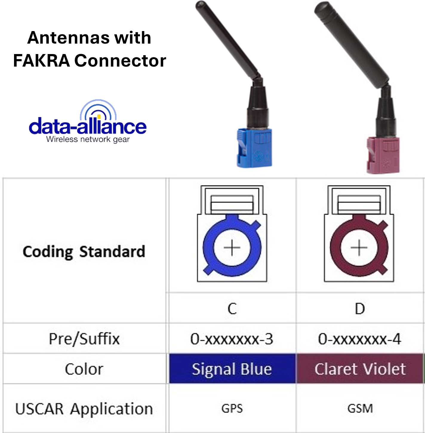
[I] Antennas with FAKRA Connector
Fakra connector antennas are designed for secure, high-performance RF connections in demanding environments such as automotive, telematics, and industrial IoT applications. Built around the standardized Fakra interface (SMB-based, color-coded connectors), these antennas provide reliable connectivity for cellular, GNSS, WiFi, and other wireless systems. A FAKRA cable may be used to extend the connection between antenna and the device's RF conenctor.
At Data Alliance, our selection of Fakra antennas supports a wide range of technologies including 5G, 4G LTE, GPS/GNSS, and WiFi, making them ideal for modern connected devices that require stable, multi-band performance.
Frequently asked questions
How are antenna connectors attached to antennas?
A robust connection must be made between the antenna elements and cabling within the antenna enclosure and the radio frequency connector. This is completed as part of the manufacturing process by soldering or crimping the connector to the radiating elements. The center pin of the antenna connector will be securely connected to the center conductor of the antenna by making a crimp connection or soldering the pin on. Soldering is often preferred for attachment of the connector as the strength of the attachment may be less likely to weaken with time and use. Technique and diligence in both crimping and soldering will prevent the inadequate application of the antenna connector with non-conforming results, impedance mismatch, and other electrical problems in the assembled antenna.
In conclusion
These common antenna connectors are critical to the performance of high-quality wireless networking equipment. Making the correct connector selection will ensure the correct functioning of the antenna and the entire radio frequency system to which it is attached.
LEARN MORE: