


U.FL to SMA Cables
SMA to U.FL Cables and Adapters
SEE LIST OF ARTICLES ABOUT U.FL CABLES AND CONNECTORS
Our SMA to U.FL cables' consistently low broadband VSWR, range of frequency band compatibility (from 0GHz to 11 GHz)and 50 Ohms impedance matching, makes them suitable for all the following applications:
- All WiFi standards:2.4GHz or 5GHz applications: Wi-Fi 6, WiFi 6E, 802.11AX, 802.11AC,802.11N, 802.11G, 802.11B,802.11A,
- Cellular Wireless LTE / 4G,LTEm,GSM / 3GWiMax, 5G
- IOT (Internet of Things)wireless protocols: Bluetooth, ZigBee, LoRa, M2M, RFID, NB-IoT.
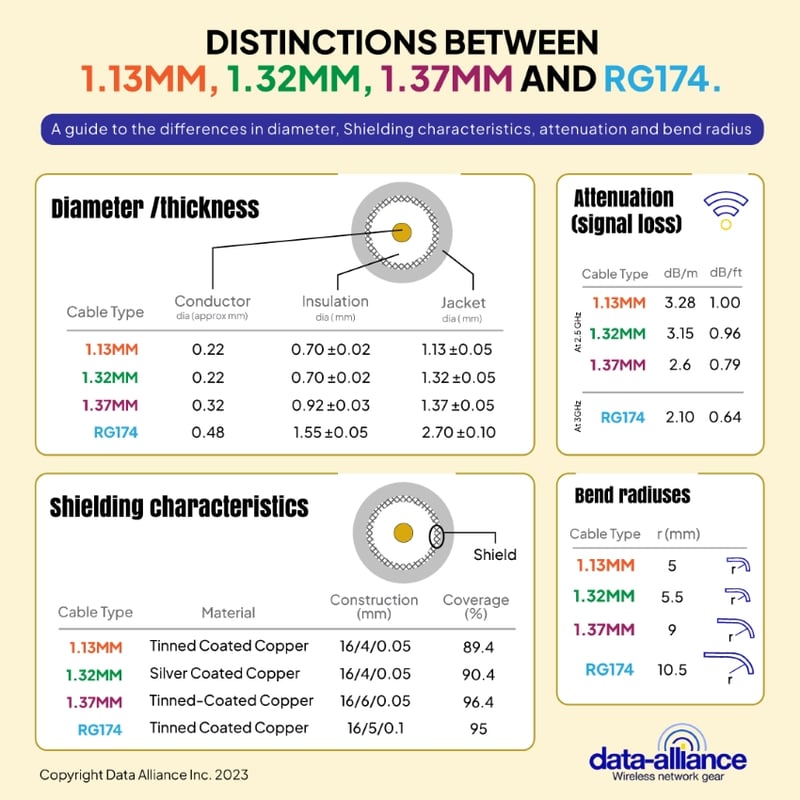
The Coaxial Cable: Data Alliance uses1.13mm coax for shorter U.FL cables. Typically for longer U.FL cables we use RG174. The 1.13mm diameter and very flexible 1.13 is sometimes a necessity - if the space is very tight inside small cases that house PCBs (Printed Circuit Boards), and mini-PCI wireless cards. A third option is 1.32mm coax, which has the benefits of double-shielding (in the form of two layers of braided sliver-plated copper) for low loss, while at the same time being very thin and flexible.
- U.FL connectors on 1.13 and 1.32 coax snap down more securely and permanently onto the jack
- U.FL connectors on RG174 are prone to popping off the jack, unless they are glued down. If you want RG174 for its low-loss characteristic, we recommend that you try RG174 in your application before making the decision.
- R174 is the thickest coax that can be used with U.FL: It is 3mm in diameter. RG174 is far less flexible than 1.13 and 1.32, but delivers less signal loss (attenuation) than 1.32mm or 1.13mm - though RG174 is not double-shielded.
Data Alliance customizes the coax option for our customers, as needed.
We also offer adapters from U.FL to SMA male and female: There is less signal loss when using an adapter than a cable, so an adapter is a better option if it fits with your application.
The U.FL Connector (sometimes referred to as the Ultra Miniature Coaxial Connector (UMCC)) is at a right-angle in all of Data Alliance's U.FL cables, and connects the antenna cable to the U.FL connector/jack on internal mini-PCI wireless cards, and Printed Circuit boards (PCB). The small profile and right angle of the female U.FL connector has made them an excellent choice for embedded wireless systems for Internet of Things (IoT). devices (such as Bluetooth beacons), and M2M (Machine to Machine) applications. IoT applications typically use very small casings and enclosures and tiny connectors are required in these cramped spaces. The male/female mated connection stands only 2.5mm high.
U.FL connectors are often found on miniature antennas, Wi-Fi modules, and PCBs due to its compact size and ability to handle high-frequency signals. Despite its small size, the U.FL connector offers excellent performance in terms of signal integrity.
The Hirose U.FL connector is one of the smallest RF connectors. It is rated for frequencies from 0 to 6Ghz.
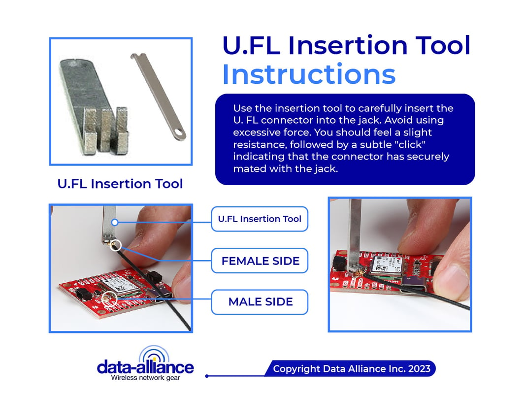
The mated connection is meant to be semi-permanent after mating, because snapping and unsnapping it several times will cause the female connector to wear out. It would then need to be replaced, along with the attached coaxial cable. Data Alliance offers a tool for inserting U.FL connectors into place.
The male connector is usually soldered directly onto the circuit board as the jack: The jack is small enough to take up as little as 9mm x 9mm of space. The female connector snaps onto the male connector, secured by pressure from the metal snap structure.
U.FL to SMA antenna cables are coaxial cables characterized by their threaded, medium-sized coupling connectors made for use from DC to 11GHz. They also have consistently low broadband Voltage Standing Wave Ratio (VSWR), which has made them one of the most popular cables for all manner of applications. The impedance of the U.FL to SMA series cables is 50 Ohms (this includes all three coax types 1.13. 1.32, and RG174).
The cables' range of frequency band compatibility and 50 Ohms impedance matching, makes them suitable for all the following applications:
- All WiFi standards: 2.4GHz or 5GHz applications: Wi-Fi 6, WiFi 6E, 802.11AX, 802.11AC, 802.11N, 802.11G, 802.11B,802.11A,
- Cellular Wireless LTE / 4G, GSM / 3G WiMax
- IoT wireless: Bluetooth, ZigBee, LoRa
U.FL PCB Board Compatibility
The U.FL female connector is compatible with the antenna jacks of a variety of PCB boards and mini-PCI cards. It connects to the U.FL LP 66 cable connector common in mini-PCI wireless cards including XBee on ZigBee radios, Ubiquiti, MikroTik, and Intel PRO WiFi cards. The U.FL jack on the card makes it possible to connect a female U.FL connector to the external antenna of your mini PCI wireless card.
The SMA Connector is a round screw type of connectors that are characterized by threaded, medium-sized coupling connectors that are suitable for frequencies of 0 GHz up to 18GHz. The antenna cable is compatible with all types of antennas including cellular voice and data, ZigBee, Bluetooth, WiFi and wireless networks, and WiMAX: 802.11n, 5GHz and 2.4GHz, and 900 MHz applications across a frequency range of between 0 to 18GHz.
SMA, or SubMiniature version A, is a standard RF connector that comes in various sizes and genders (SMA male and SMA female). It is widely used in the electronics industry for its durability and versatility. SMA connectors are often employed in RF applications, including antennas, signal testing, and connections between different components in RF systems.
We offer U.FL to SMA-female and U.FL to SMA-male cables. All of ourSMA-female connectors come with a brass bulkhead nut and washer, which can be used to mount the connector in the port of a case or enclosure wall: A rubber o-ring can be added on the exterior to weatherproof and dust-proof the port, to IP68 weatherproof rating.
We offer these cables with SMA connectors either straight or right angled:
- U.FL to SMA-female straight
- U.FL to SMA-female right-angled
- U.FL to SMA male straight
- U.FL to SMA-male right angled
Our U.FL connectors and SMA connectors are gold plated for minimal signal loss.
How to Prevent U.FL Connectors from Detaching from the Cable or the Jack
U.FL connectors are designed for a limited number of mating cycles and can easily become detached if mishandled or subjected to mechanical stresses. Here's how you can address the issue of a U.FL connector that easily detaches from the cable:
-
Ensure Proper Installation
- Always use a U.FL mating tool if possible. This reduces the risk of damaging the connector by applying too much force or at the wrong angle.
- Ensure that the connector is fully seated. When it's correctly connected, you'll feel a slight 'click'.
- Do not twist the connector. U.FL connectors should be connected straight-on, without any rotation.
-
Secure the Cable
- Using a small piece of adhesive tape or glue can help keep the U.FL connector in place. However, be cautious not to get adhesive on the connector itself.
- Some boards have an adhesive pad right next to the U.FL connector for this exact purpose.
-
Strain Relief
- Ensure that the cable has some slack near the U.FL connector. This reduces mechanical stress.
- Use cable ties or clips to secure the cable, ensuring that any pulling force does not directly affect the U.FL connection.
-
Inspect for Damage
- Check both the cable and connector for signs of damage. If either looks worn out or damaged, consider replacing them.
- Avoid bending the cable sharply near the connector, as this can weaken the connection.
-
Consider Reinforcement
- For applications where mechanical stress is a known issue, you might want to look into connectors that come with a locking feature or a more robust design.
- There are also snap-on or clip-on retainers available that can add an additional layer of security.
-
Limit Mating Cycles
- U.FL connectors are not designed for frequent connections and disconnections. They're typically rated for around 30 to 50 mating cycles. If you need to connect and disconnect frequently, consider an alternative connector type.
-
Environmental Protection
- Ensure the connector is not exposed to harmful environmental conditions, like moisture or dust, that could degrade the connection.
-
Check for Proper Fit
- Not all U.FL connectors are created equal. There are variations between manufacturers. Ensure that your cable and board-side connectors are compatible and fit snugly.
-
Consider an Alternative
- If you continue to have issues and the application permits, consider transitioning to a more robust connector type, like SMA or MMCX, which are designed to handle more mating cycles and mechanical stress.
-
Educate the Users
- If the device is being used or serviced by multiple individuals, ensure that they are educated about the delicate nature of the U.FL connectors.
By addressing these factors, you can mitigate the risk of a U.FL connector detaching from its cable. If you're designing a product or system, always account for mechanical stresses in your design, especially if the device will be subjected to movement or frequent handling.
The Role of U.FL to SMA Cables
U.FL to SMA cables serve as the bridge between these two connector types, allowing designers and engineers to connect devices equipped with U.FL connectors to standard SMA interfaces. These cables play a crucial role in various applications:
-
Wireless Communication: U.FL to SMA cables are commonly used in wireless communication systems, such as Wi-Fi routers, cellular modems, and Bluetooth devices. They enable the connection between miniature U.FL antenna connectors and external SMA antennas, improving signal strength and coverage.
-
RF Testing and Measurement: In the field of RF testing and measurement, SMA connectors are the industry standard. U.FL to SMA cables facilitate the connection of test equipment to PCB-mounted U.FL connectors, ensuring accurate signal analysis and measurements.
-
GPS and GNSS Devices: Global Positioning System (GPS) and Global Navigation Satellite System (GNSS) devices often use U.FL connectors for their compact form factor. U.FL to SMA cables allow these devices to connect to external antennas for enhanced accuracy and reception.
Key Considerations when Using U.FL to SMA Cables
When working with U.FL to SMA cables, several important considerations must be kept in mind:
-
Cable Length: The length of the cable can affect signal integrity and performance. It's essential to choose the appropriate cable length for your specific application to minimize signal loss.
-
Frequency Range: Different U.FL to SMA cables have varying frequency ranges. Ensure that the cable you select can handle the frequencies required for your application.
-
Connector Types: Verify the gender and compatibility of the U.FL and SMA connectors on both ends of the cable to ensure a proper fit.
-
Signal Loss: U.FL to SMA cables introduce some signal loss due to their length and the characteristics of the cable itself. Be aware of the potential signal degradation and plan accordingly.
Conclusion
In the world of electronics, connectivity is key. From Wi-Fi routers to GPS receivers, many devices rely on the seamless transmission of signals and data to function effectively. One crucial component that often goes unnoticed but plays a pivotal role in ensuring this connectivity is the U.FL to SMA cable. These miniature cables are responsible for bridging the gap between small, high-frequency connectors like U.FL (also known as IPX) and standard SMA connectors, facilitating reliable communication in a wide range of applications.
In this article, we will delve into the world of U.FL to SMA cables, exploring their significance, applications, and the key considerations when using them in your projects.
Understanding U.FL and SMA Connectors
Before diving into U.FL to SMA cables, let's first understand the connectors involved.
-
U.FL (IPX) Connector: U.FL, short for Ultra Miniature Coaxial, is a tiny coaxial RF (radio frequency) connector commonly used in wireless communication systems. It is often found on miniature antennas, Wi-Fi modules, and PCBs due to its compact size and ability to handle high-frequency signals. Despite its small size, the U.FL connector offers excellent performance in terms of signal integrity.
-
SMA Connector: SMA, or SubMiniature version A, is a standard RF connector that comes in various sizes and genders (SMA male and SMA female). It is widely used in the electronics industry for its durability and versatility. SMA connectors are often employed in RF applications, including antennas, signal testing, and connections between different components in RF systems.
The Role of U.FL to SMA Cables
U.FL to SMA cables serve as the bridge between these two connector types, allowing designers and engineers to connect devices equipped with U.FL connectors to standard SMA interfaces. These cables play a crucial role in various applications:
-
Wireless Communication: U.FL to SMA cables are commonly used in wireless communication systems, such as Wi-Fi routers, cellular modems, and Bluetooth devices. They enable the connection between miniature U.FL antenna connectors and external SMA antennas, improving signal strength and coverage.
-
RF Testing and Measurement: In the field of RF testing and measurement, SMA connectors are the industry standard. U.FL to SMA cables facilitate the connection of test equipment to PCB-mounted U.FL connectors, ensuring accurate signal analysis and measurements.
-
GPS and GNSS Devices: Global Positioning System (GPS) and Global Navigation Satellite System (GNSS) devices often use U.FL connectors for their compact form factor. U.FL to SMA cables allow these devices to connect to external antennas for enhanced accuracy and reception.
Key Considerations when Using U.FL to SMA Cables
When working with U.FL to SMA cables, several important considerations must be kept in mind:
-
Cable Length: The length of the cable can affect signal integrity and performance. It's essential to choose the appropriate cable length for your specific application to minimize signal loss.
-
Frequency Range: Different U.FL to SMA cables have varying frequency ranges. Ensure that the cable you select can handle the frequencies required for your application.
-
Connector Types: Verify the gender and compatibility of the U.FL and SMA connectors on both ends of the cable to ensure a proper fit.
-
Signal Loss: U.FL to SMA cables introduce some signal loss due to their length and the characteristics of the cable itself. Be aware of the potential signal degradation and plan accordingly.
U.FL to SMA cables may be small in size, but their role in facilitating connectivity in various electronic applications is undeniable. Whether you're working on a wireless communication project, RF testing, or enhancing the performance of your GPS device, these cables serve as essential components that bridge the gap between different connectors, ensuring efficient signal transmission and maintaining the integrity of your electronic systems. By understanding their significance and considering the key factors when using them, you can make informed choices to optimize your electronic designs and projects.