


RP-SMA Extension Cable: 2-inch 3-in, 4-in, 5-in, 6-in 8-inch. Male To Female
- SKU:
- RSm2iRSf100
- Availability:
- In stock
- Weight:
- 0.03 LBS
Data Alliance


RP-SMA Male to Female Cables: 3 inches to 8 inches
- One end has an RP SMA male connector, and the other has an RP SMA female connector with a bulkhead nut and washer for mounting and weatherproofing. The connectors are straight RP-SMA male and straight RP-SMA female.
- Other lengths of our RP-SMA extension cables from inches to meters.
- The cable length stated in the length options is between the connectors. Data Alliance's RP-SMA connectors are not just standard but high-quality. Our cables feature soldered terminations, ensuring a low-loss connection with minimal discontinuities. This construction guarantees the durability and performance of our cables, making them a reliable and secure choice for your wireless setup.
- If you need an O-ring embedded in the flange of the female connector, for a weatherproof seal: We offer this option for the 8-inch version and we can offer for other versions for large orders (contact Customer Service). The version with an O-ring embedded has a larger diameter flange of the female connector.
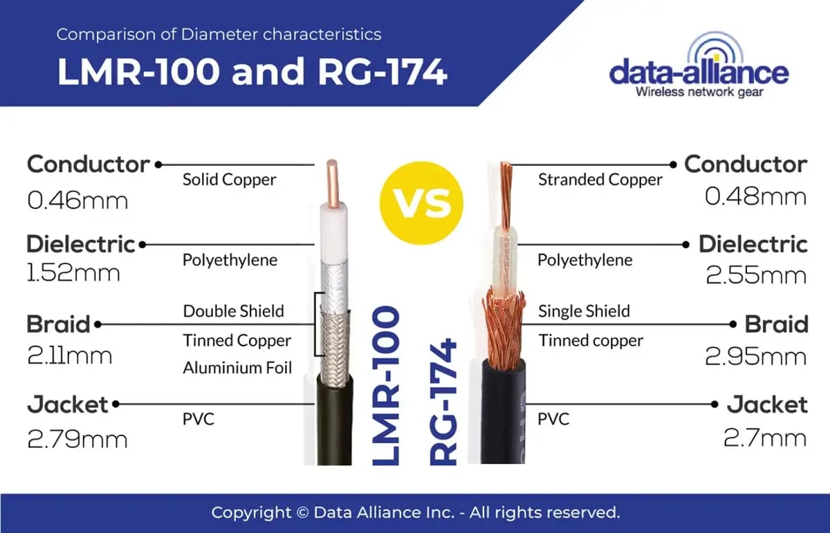
The cable is double-shielded, low-loss, and very flexible/easily bendable. The cable type is equivalent to or better than LMR100: Coax with a black jacket has the same or better signal loss per meter and flexibility as LMR100 and less attenuation (signal loss) than RG174. The higher quality of this antenna cable coax translates into lower loss/better performance. The cable is equivalent to LMR-100 in thickness. This cable is rated for outdoor use and is also suitable for indoor use. The impedance is 50 Ohms.
The temperature range for operational use of this 100-series coax and the cable assembly is -22 F ~ +185 F (-30 C ~ +85 C)
RP-SMA female connector includes a bulkhead nut and washer for mounting & waterproofing:
- You can use this hardware to mount the connector (and thus the cable) on the wall of a network enclosure (to weatherproof the cable connection) or mount the connector on a case, panel, or Printed Circuit Board (PCB).
- Weatherproofing: Seal the hole where the female connector is mounted by placing an O-ring between the enclosure's wall and the bulkhead nut and washer on the female connector.
- The length of our standard RP-SMA-female connector (threaded part) is 3/8 inches. We have a longer option, 14.5mm, which is available. The longer 14.5mm option has an O-ring embedded in the flange to waterproof the port where the cable enters a network enclosure.
- All our cables with SMA and RP-SMA female connectors have bulkhead mount hardware.
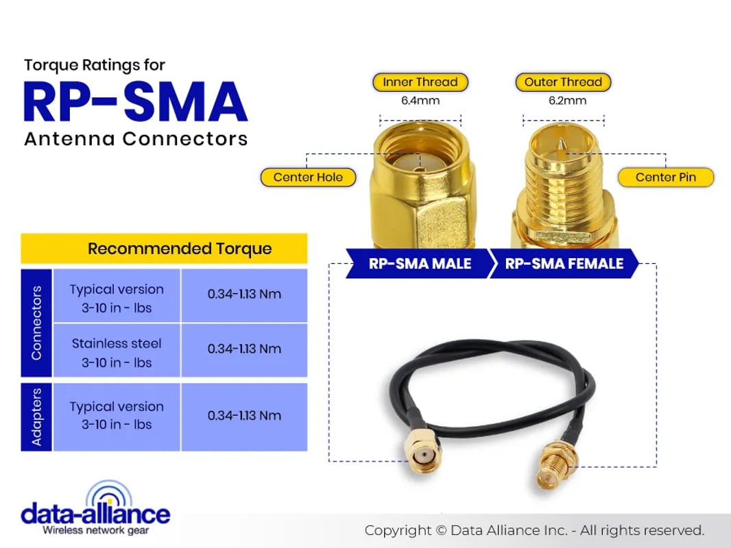
RP SMA Features and Key Information, including connector dimensions and materials composition
Compatibility with wireless standards & applications:
- All WiFi standards: 2.4GHz and 8GHz applications: Wi-Fi HaLow 802.11AH, Wi-Fi 6, WiFi 6E, 802.11AX, 802.11AC, 802.11N, 802.11G, 802.11B, 802.11A
- Cellular Wireless LTE / 4G, GSM / 3G WiMAX: Data and voice applications
- IoT wireless & M2M: Bluetooth, ZigBee, Wi-Fi HaLow, RFID, LoRa, LTE-m, NB-IoT.
- Compatible with all Helium miners used in North America, including Bobcat miners, Sensecap miners, and all other Helium LongFi miners, as are all of our antenna cables and adapters with RP-SMA-male connectors
Our RP-SMA extension cables' range of frequency band compatibility (from 0 to 18GHz), consistently low broadband VSWR, and impedance matching to 50 Ohm antennas and cables make them suitable and compliant for all the above applications.
At Data Alliance, we prioritize your safety and the environment. That's why our antenna cables comply with ROHS 3 and REACH restrictions on lead content, other heavy metals, and toxic materials. This commitment to safety and environmental responsibility reassures you that our products are high quality and safe for you and the environment.
Setting up our RP-SMA male-to-female extension cable is a breeze. The RP-SMA male connector is designed to fit most Wi-Fi routers' jacks. In contrast, the RP-SMA female connector is perfectly compatible with the male connector on antennas with an RP-SMA male connector. This straightforward installation lets you position the antenna further from the router, optimizing your wireless signal.
RP-SMA EXTENSION CABLE RELATED PRODUCTS:
RELATED PRODUCTS PAGES:
- RP-SMA right-angle adapters and cables
- RP-SMA extension cables
- SMA Adapters
- SMA Cables, Antennas and Connectors
Frequently Asked Questions
What is the typical VSWR (Voltage Standing Wave Ratio) for these cables, and why does it matter?
The typical VSWR for these cables is 1.2:1. A low VSWR indicates efficient transmission with minimal signal reflection, ensuring better performance in RF applications.
How does the dielectric constant of the cable materials impact the signal transmission?
The dielectric constant affects the velocity factor and the characteristic impedance of the cable. A lower dielectric constant, as found in PTFE, reduces signal loss and improves performance.
What is the bending radius of these cables, and how does exceeding it affect the cable?
The minimum bending radius is typically 5 times the cable diameter. Exceeding this radius can cause permanent deformation of the dielectric, leading to increased insertion loss and potential cable failure.
How does the connector plating material influence signal integrity and durability?
Gold plating on the connectors enhances signal integrity by providing a low-resistance path and preventing oxidation. This ensures long-term reliability and consistent performance.
What is the maximum frequency range these cables can support, and what factors limit this range?
These cables can support frequencies up to 18 GHz. The frequency range is limited by factors such as the quality of the materials, the precision of the manufacturing process, and the cable length.
How do these cables perform in terms of PIM (Passive Intermodulation), and why is this important?
These cables are designed to minimize PIM, with typical values below -155 dBc. Low PIM is crucial in environments where multiple signals coexist, as it reduces interference and improves overall system performance.
How do the phase stability and phase noise characteristics of these cables affect high-precision applications?
High phase stability and low phase noise are essential for applications requiring precise timing and signal synchronization. These cables are designed to offer minimal phase variation over temperature changes and mechanical flexing.
What are the EMI (Electromagnetic Interference) shielding capabilities of these cables, and how are they tested?
The cables offer excellent EMI shielding, typically achieving >90 dB attenuation. This is tested using standardized procedures like the transfer impedance method, ensuring minimal interference in high-noise environments.
How do these cables handle power dissipation, and what are the implications for high-power applications?
The cables are designed to handle power dissipation efficiently, with a typical power rating of up to 50W at 2.4 GHz. Proper heat dissipation is critical to prevent overheating and maintain signal integrity in high-power applications.