


Antennas, Antenna Cables, Wireless Products: Technical Articles
LMR-400 Cable: How to Choose and Spec a Low-Loss Coax Assembly
An LMR-400 cable is a 50-ohm, low-loss RF coaxial assembly (roughly 0.405 in / 10.3 mm outer diameter) that integrators reach for when a run is too long for thin coax like RG-174 or LMR-240, but doesn't justify the cost and stiffness of LMR-600. It pairs low attenuation with a bend radius you can still work with in the field, which is why it's the default feedline for Wi-Fi, LoRa, LTE/cellular, GPS and point-to-point links. This guide walks through the specs that actually drive the buying decision — loss per 100 ft by frequency, connector options, bend radius, and when LMR-400 is the wrong choice.
What makes LMR-400 cable the default low-loss coax
LMR-type coax uses a solid center conductor, a foam polyethylene dielectric, and a bonded aluminum-foil-plus-braid shield. That construction is what gives an LMR-400 cable its two headline traits: low loss per unit length and a shielding effectiveness high enough for dense RF environments. The trade-off is flexibility — a ~0.4 in cable does not bend like a jumper, so you plan the route before you order the length.
Key electrical and mechanical figures to verify on any assembly you buy:
- Impedance: 50 ohm (match it to your radio and antenna — a 75-ohm substitution introduces a mismatch).
- Outer diameter: ~0.405 in (10.3 mm).
- Minimum bend radius: roughly 1.0 in (25 mm) for repeated bends; tighter one-time installs may allow less — confirm the manufacturer's rating before routing through conduit.
- Frequency range: usable well into the low-GHz range; manufacturers typically rate the family to ~6 GHz. Verify the spec for your band.
- Velocity of propagation: ~85% (useful if you are cutting phase-matched lengths).
LMR-400 cable loss: the number that drives the decision
Attenuation rises with frequency, so the same physical run costs you more dB at 5 GHz than at 900 MHz. Use representative figures for budgeting, then confirm against the exact datasheet for the cable you order — values vary slightly by manufacturer and by temperature.
| Frequency | Approx. attenuation (dB / 100 ft) | Typical use |
|---|---|---|
| 150 MHz | ~1.5 | VHF / land mobile |
| 450 MHz | ~2.7 | UHF / telemetry |
| 900 MHz | ~3.9 | LoRa 915 MHz, GSM |
| 1800 MHz | ~5.4 | LTE / cellular |
| 2400 MHz | ~6.6 | 2.4 GHz Wi-Fi, Bluetooth, Zigbee |
| 5800 MHz | ~10.8 | 5 GHz Wi-Fi, 5.8 GHz links |
These are nominal, published-class figures for the LMR-400 family — treat them as planning numbers, not guarantees, and pull the exact datasheet before you finalize a link budget. The practical takeaway: a 100 ft run at 5.8 GHz can eat ~10 dB, which can wipe out a high-gain antenna's advantage. Shorten the run, mount the radio closer to the antenna, or step up to lower-loss coax.
Choosing connectors for an LMR-400 cable
LMR-400 terminates cleanly into the larger, rugged connector families — which is a big part of why it's used outdoors and on tower runs. The common choices:
- N-type: the workhorse for LMR-400. Weatherproof, 50-ohm, rated well into the low-GHz range, and sized to match the cable. Most outdoor antenna runs use N-male on the cable.
- SMA / RP-SMA: common at the radio end where the device has an SMA bulkhead. You'll often see an N-to-SMA assembly or a short SMA jumper off a main N-terminated run.
- TNC / RP-TNC: a threaded, more vibration-resistant alternative to SMA for mobile and rugged installs.
For a deeper comparison of how these families differ in frequency ceiling and ruggedness, see our breakdown of SMA vs N-type vs TNC vs BNC connectors. If your run terminates into video or legacy test gear instead, our guide to 50-ohm vs 75-ohm BNC cables explains why impedance matters at the connector too.
How to spec an LMR-400 cable: a selection flow
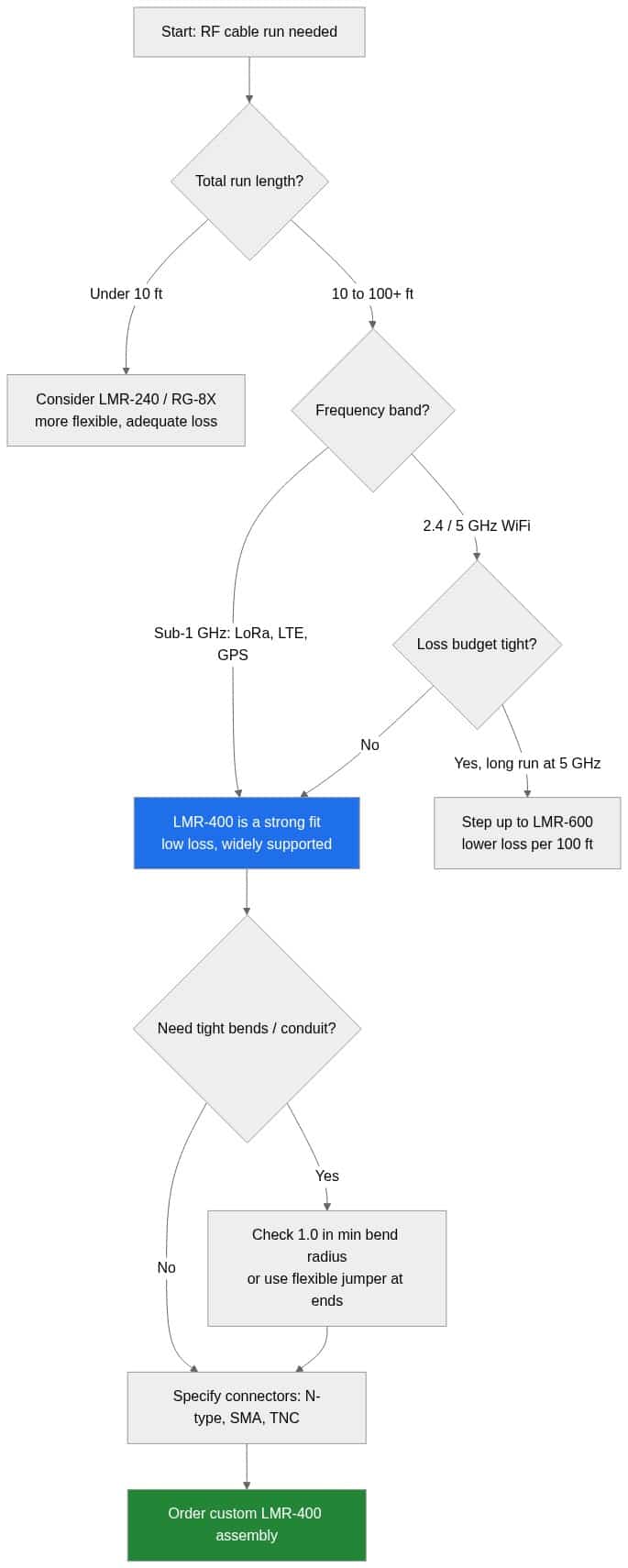
Work through length, frequency, loss budget and connectors in that order. The flowchart below captures the decision path integrators actually follow.
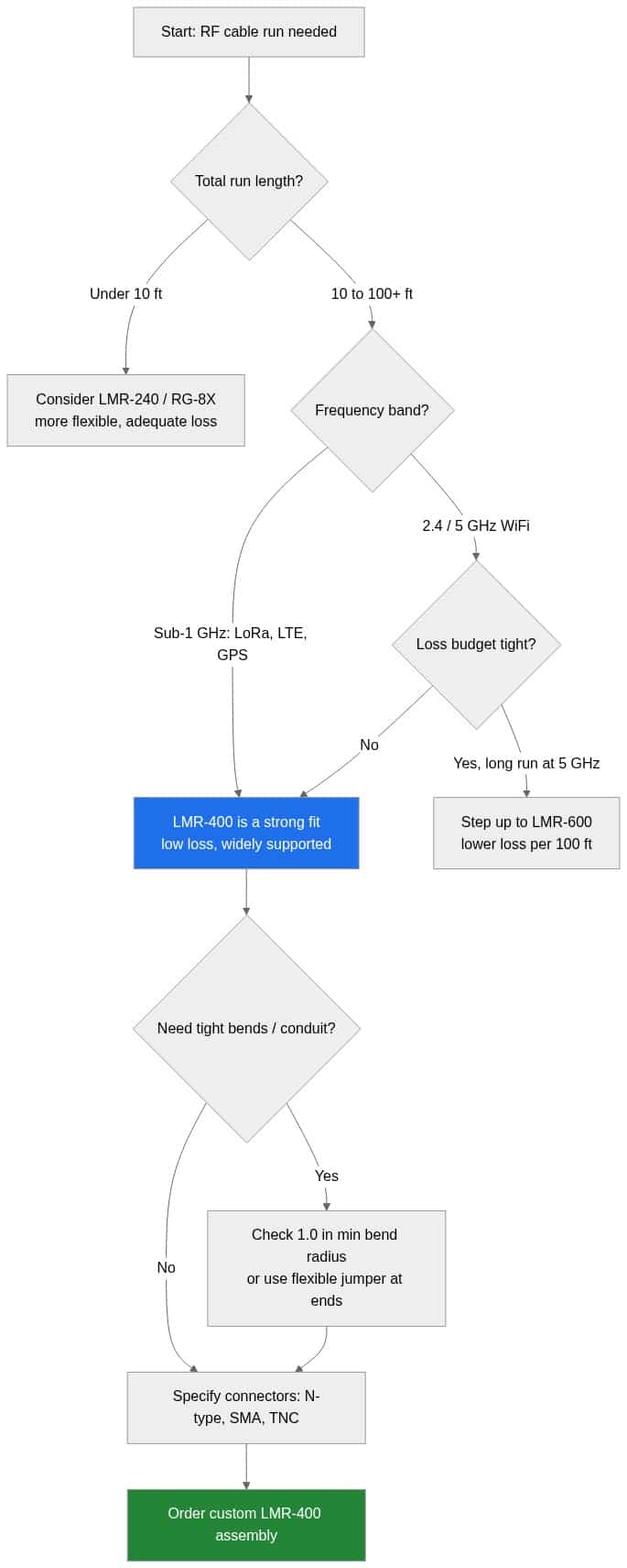
- Measure the real run length — including slack, drip loops and the vertical rise up a mast. Order exactly; every extra foot is extra loss.
- Fix your operating frequency and read the loss off the table above.
- Compute the link budget: antenna gain minus cable loss minus connector/mismatch loss. If the number leaves no margin, shorten the run or move to LMR-600.
- Pick connectors to match the radio and antenna ports — N-type at the antenna is the safe default outdoors.
For the full method across every coax family, see our LMR-400 coax specifications reference and the companion RG-174 vs LMR-100 shielding and loss comparison for the thin-coax end of the range.
LMR-400 vs LMR-600 and thinner coax: when to switch
| Cable | Approx. OD | Relative loss | Best for |
|---|---|---|---|
| RG-174 / LMR-100 | ~0.10 in | Highest | Short internal jumpers, U.FL pigtails |
| LMR-240 | ~0.24 in | Moderate | Short-to-medium flexible runs |
| LMR-400 | ~0.405 in | Low | Medium-to-long outdoor runs — the default |
| LMR-600 | ~0.59 in | Lowest (of these) | Long runs / high frequency where every dB counts |
Rule of thumb: if the loss table leaves your link budget with little margin at your frequency and length, step up a size. If flexibility and cost matter more than the last dB on a short run, step down. For the detailed numbers on the heavier option, see our LMR-300 and LMR-600 coax specifications guide.
Where LMR-400 cable gets used
Because it balances loss and handling, LMR-400 is common in long-range outdoor Wi-Fi backhaul, LoRa/LoRaWAN gateway feedlines, GPS timing installs, and cellular antenna runs. If you're feeding an LTE/4G router from a rooftop antenna, LMR-400 at sub-2 GHz keeps loss manageable over a realistic run. Browse ready-made and custom options in Antenna Cables & Adapters, or for N-terminated runs specifically, our N-type cables & adapters category.
Need an exact length with specific end connectors? Data Alliance custom-manufactures LMR-400 assemblies to order — configure a cable and add it to your cart, or contact technical support for a custom quote with your length, connector and frequency requirements.
Frequently asked questions about LMR-400 cable
Is LMR-400 cable 50 ohm or 75 ohm?
LMR-400 is a 50-ohm coax, which matches virtually all RF radios, Wi-Fi, cellular and antenna systems. Don't substitute 75-ohm cable (used for video/CATV) on a 50-ohm RF path — the impedance mismatch raises VSWR and reflects power back toward the radio.
How much signal does LMR-400 lose over 100 feet?
It depends entirely on frequency. As a planning guide, expect roughly 3.9 dB/100 ft at 900 MHz, ~6.6 dB/100 ft at 2.4 GHz, and ~10.8 dB/100 ft at 5.8 GHz. Always confirm against the exact datasheet for the cable you buy before finalizing a link budget.
What connectors can I put on an LMR-400 cable?
LMR-400 terminates into N-type (most common outdoors), SMA/RP-SMA (common at the radio), and TNC/RP-TNC. The right choice is whatever matches your radio and antenna ports; N-male at the antenna end is the typical outdoor default.
When should I use LMR-600 instead of LMR-400?
Step up to LMR-600 when your run is long and your frequency is high enough that LMR-400's loss eats your link budget — for example, a long 5 GHz run. LMR-600 has lower loss per 100 ft but is thicker, stiffer and more expensive, so only use it when the extra margin is needed.
What is the minimum bend radius of LMR-400?
Plan for roughly a 1.0 in (25 mm) minimum bend radius for repeated bends; one-time installation bends may allow tighter. Verify the exact figure on the manufacturer datasheet, and use a short flexible jumper at the ends if you need tight routing into equipment.