


Antennas, Antenna Cables, Wireless Products: Technical Articles
0.81mm Coaxial Cable for W.FL and MHF3 Cable Assemblies
Table of Contents
0.81 Coax Specifications, Key Features, Applications
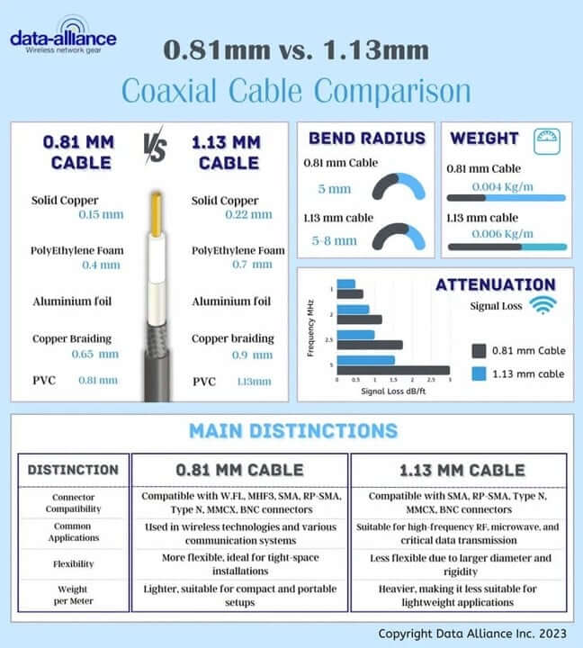
The 0.81 coaxial cable is the typical coax used for W.FL cables and MHF3 cable assemblies. This article provides an in-depth understanding of the 0.81 coaxial cable, focusing on its compatibility with IoT wireless technologies, key features, material composition, and applications. It is also used for MHF4 cables.
The thickest, lowest-loss coax that can accommodate W.FL and MHF3. 0.81 coax is very rarely used for U.FL cables, because U.FL connectors can accommodate larger-diameter coax types, with better attenuation characteristics."
Compatible Wireless Technologies
The 0.81 coaxial cable stands out for its capability to support a variety of wireless technologies and protocols, ensuring robust and stable communication within diverse application contexts. Below is an outline that organizes and highlights its compatibility and applications across various wireless protocols and technologies.
I. Wi-Fi Technologies
A. Wi-Fi 4 (802.11n)
1. Employed in both residential and commercial wireless networks.
2. Usage in devices like routers and access points.
B. Wi-Fi 5 (802.11ac)
1. Known for high-throughput wireless networks.
2. Utilization in high-speed data transmission applications.
C. Wi-Fi 6 (802.11ax)
1. Emphasis on improving network capacity.
2. Adoption in environments with dense user access.
II. Cellular Technologies
A. 3G (Third Generation):
- Legacy systems in remote and developing areas.
- In applications that require minimal data transmission.
B. 4G/LTE and LTE-m: Prevalent in modern telecommunications. Critical for high-speed internet access and data communication.
C. 5G: Adoption in next-gen applications, including IoT and smart cities. Utilization in applications demanding ultra-reliable low-latency communication.
III. Bluetooth Technologies
A. Classic Bluetooth
1. Utilized for short-range communication between devices.
2. Applicable in peripherals, audio devices, and automotive applications.
1. Designed for applications that require minimal power consumption.
2. Widely used in wearables, sensors, and smart home applications.
IV. Internet of Things (IoT) Technologies
A. Zigbee
1. Notable for low-cost, low-power wireless mesh networks.
2. Applied in smart home, industrial automation, and low-bandwidth applications.
1. Utilized for long-range communication in IoT networks.
2. Applicable in agriculture, smart cities, and environmental monitoring.
1. Employed for wide-area networks to connect various IoT devices.
2. Usage in smart metering, smart parking, and utility monitoring.
V. Satellite Communication Technologies
A. C-Band
1. Utilized for satellite communication, especially in television transmission
2. Applies in direct-to-home broadcasting and satellite internet
B. X-Band
1. Primarily used for military communication and weather monitoring
2. Integration in radar applications and satellite communication
VI. Radio Communication Technologies
A. VHF (Very High Frequency)
1. Adoption in maritime and aviation communication
2. Applied in line-of-sight ground communication
B. UHF (Ultra High Frequency)
1. Utilized for broadcasting and emergency communication
2. Engaged in military, public service, and commercial applications
Materials Composition
I. Inner Conductor
A. Material
1. Typically made of copper
2. Alternatives like aluminum may be used
B. Characteristics
1. High electrical conductivity
2. Essential for transmitting the signal
II. Dielectric Insulator
A. Material
1. Commonly polyethylene or PTFE
2. Other high-insulation materials may be utilized
B. Function
1. Prevents signal loss by isolating the inner conductor
2. Maintains the conductor’s position, ensuring consistent impedance
C. Characteristics
1. High resistance to electrical conductivity
2. Stability across varied temperatures
III. Shielding
A. Material
1. Often comprised of aluminum or copper braiding
2. May include a foil layer for additional shielding
B. Purpose
1. Guards against external electromagnetic interference (EMI)
2. Protects against radio frequency interference (RFI)
C. Types
1. Braided Shield: Composed of woven strands of metal
2. Foil Shield: A layer of aluminum or metallic foil
3. Dual Shield: Incorporates both braided and foil shields
IV. Outer Jacket
A. Material
1. Frequently made of PVC
2. Other materials like PE, used based on application requirements
B. Role
1. Protects the inner layers from physical damage and environmental factors
2. Provides insulation to prevent unintended conductivity
C. Characteristics
1. Resistant to physical wear and tear
2. Ability to withstand varied environmental conditions
Attenuation Characteristics
1. Frequency-Dependent Attenuation
- Higher Frequency, Higher Attenuation: 0.81 coaxial cables, when used in MHF4 assemblies, tend to have an increase in attenuation as the frequency of the signal increases. This is a common characteristic of coaxial cables and is especially vital to consider in applications that utilize higher frequency bands.
2. Material Impact on Attenuation
- Dielectric Material: The type of dielectric material used in the 0.81 coaxial cable impacts its attenuation characteristics. Materials that have a low dielectric constant can help to minimize attenuation.
- Conductor Material: Similarly, the material used for the inner conductor will also impact attenuation. Generally, conductors with higher electrical conductivity, such as silver-coated copper, can help reduce signal loss.
3. Temperature Impact
- Variable Attenuation: The attenuation characteristics of 0.81 coaxial cables in MHF4 assemblies may vary with temperature fluctuations. Different operational environments, especially those with extreme temperatures, may influence the level of signal loss.
4. Cable Length
- Direct Proportionality: Attenuation is directly proportional to the length of the cable. Longer cables will inherently have higher attenuation compared to shorter ones. In applications where signal integrity is paramount, utilizing the shortest possible cable length is advisable.
5. Connectors and Adapters
- Additional Attenuation: The connectors and adapters used in the MHF4 cable assembly can also introduce additional attenuation. Therefore, the selection of high-quality connectors that are specifically designed to minimize signal loss is crucial.
6. Installation Impact
- Bending and Coiling: The way the cable is installed can impact attenuation. Excessive bending or coiling of the cable can result in increased signal loss, especially in high-frequency applications.
7. Shielding Effectiveness
- EMI and RFI Protection: Effective shielding is essential to protect the signal from external electromagnetic interference (EMI) and radiofrequency interference (RFI), which can also contribute to attenuation.
8. Signal Reflection
- Impedance Mismatch: Attenuation can also be affected by signal reflection caused by impedance mismatches within the cable assembly. Ensuring that components are impedance-matched helps in minimizing reflections and maintaining signal integrity.
Connector Types:
MHF4 cable assemblies, with the other connector type, chosen based on frequency, impedance, and application, being any of of the following: SMA, RP-SMA, Type N, MMCX, BNC, U.FL
Key Features & Attributes
The 0.81 coaxial cable encompasses several key features that contribute to its widespread use and reliability in RF signal transmission. Noteworthy among these are:
- Thin enough to accommodate the assembly of W.FL, MHF3 cables.
- Used for short antenna cables, being the thinnest of the coax and with a very thin diameter conductor wire.
- High-Frequency Performance: Enables the transmission of signals at higher frequencies with minimal loss.
- Impedance Stability: Ensures consistent impedance, minimizing reflections and maintaining signal integrity.
- Resistance to EMI: Provides a shield against external electromagnetic interference, safeguarding the transmitted signals.
- 0.81 coax is very rarely used for U.FL cables, because U.FL connectors can accommodate larger-diameter coax types, including 1.13mm, 1.32mm, 1.37mm and RG174.
- 0.81 coax is not used for SMA cables nor RP-SMA cables unless the other connector is W.FL or MHF3.
The 0.81 coaxial cable, with its distinctive layered structure, facilitates reliable and high-quality signal transmission in various applications across industries. From the internal conductor transmitting the RF signal to the external jacket protecting the internal components and insulating the cable, each layer plays a critical role in ensuring effective and stable signal transmission and protection against potential interferences and physical damages. It's the combination of these structural elements that culminate in the cable's widespread adoption and efficacy across numerous applications and environments.
In Conclusion
0.81 mm coax is the thinnest, lowest-loss option that still fits W.FL and MHF3 terminations—ideal for short, space-constrained antenna leads where consistent 50 Ω impedance and solid EMI shielding matter. It’s only rarely paired with U.FL (which favors larger, lower-loss mini-coax) and isn’t used with SMA/RP-SMA unless the opposite end is W.FL or MHF3. Built from a high-conductivity center conductor, low-loss dielectric, robust shielding, and a protective jacket, it delivers dependable RF performance across Wi-Fi, cellular (3G–5G/LTE-M), Bluetooth/BLE, IoT stacks (Zigbee, LoRa, NB-IoT), satellite, and VHF/UHF. As with any micro-coax, keep runs short, avoid tight bends, choose quality connectors, and maintain impedance matching to minimize attenuation and reflections.
FAQs
What is 0.81 coax and where is it typically used?
0.81 mm coax is the thickest, lowest-loss micro-coax that still fits W.FL and MHF3 connectors. It’s also used in MHF4 assemblies, and only rarely with U.FL (which accepts larger, lower-loss mini-coax).
Which wireless technologies does 0.81 coax support?
It’s suitable for Wi-Fi 4/5/6, cellular (3G, 4G/LTE/LTE-M, 5G), Bluetooth Classic/BLE, IoT (Zigbee, LoRa, NB-IoT), satellite bands (C, X), and VHF/UHF radio links.
When should I choose 0.81 over other mini-coax sizes?
Choose 0.81 when you need W.FL or MHF3 terminations and very short, space-constrained runs with better loss than thinner options. For U.FL, larger cables (1.13, 1.32, 1.37 mm, RG174) are usually preferred due to lower attenuation.
What factors affect attenuation with 0.81 coax, and how do I minimize it?
Attenuation rises with frequency, temperature, length, poor connectors/adapters, tight bends, weak shielding, and impedance mismatch. Keep cables short, avoid sharp bends/coils, use quality/matched connectors, and ensure good shielding and 50 Ω impedance control.
How is 0.81 coax constructed?
It has a high-conductivity inner conductor (typically copper), a low-loss dielectric (PE or PTFE), shielding (braid, foil, or dual), and an outer jacket (often PVC or PE) for mechanical and environmental protection.
What connector pairings are common?
Commonly W.FL, MHF3, or MHF4 on one end; the other end can be SMA, RP-SMA, Type N, MMCX, BNC, or U.FL as the application dictates. Note: 0.81 is not used for standalone SMA/RP-SMA jumpers unless the opposite end is W.FL or MHF3.