


Antennas, Antenna Cables, Wireless Products: Technical Articles
LoRaWAN Antenna Guide: How to Choose by Band, Gain, Pattern & Connector
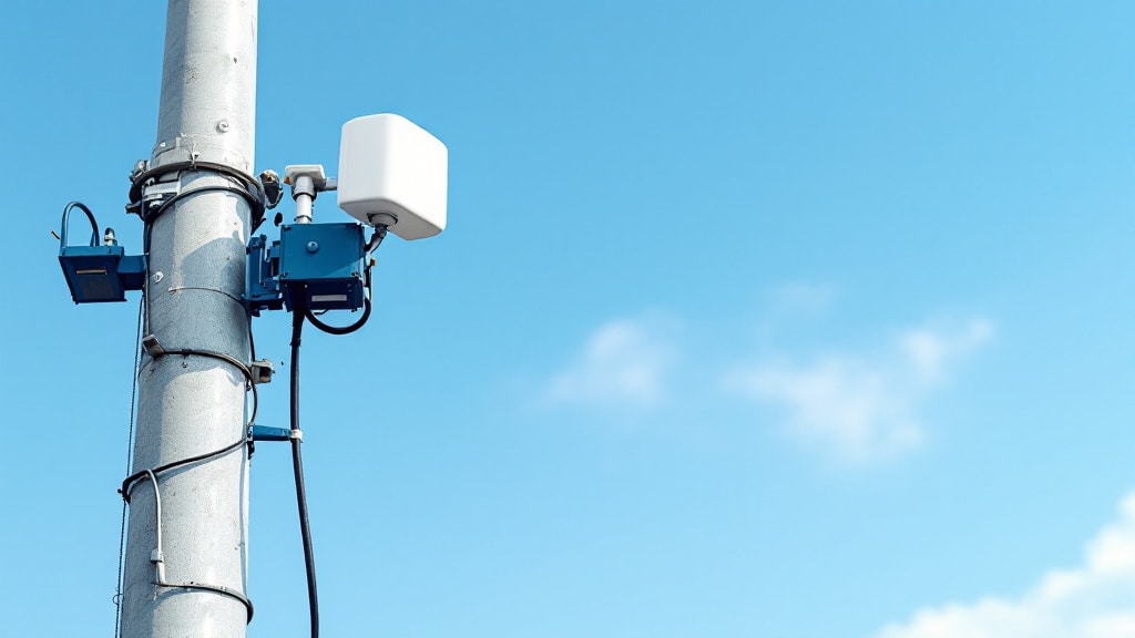
A LoRaWAN antenna is a sub-GHz antenna tuned to the unlicensed ISM band your LoRaWAN network operates in — 915 MHz (902–928 MHz) in North America, 868 MHz (863–870 MHz) in Europe, and 433 MHz in parts of Asia. Because LoRaWAN links are built to run for kilometers at very low power, the antenna, its gain, its radiation pattern, and the feedline you pair with it often matter more to real-world range than the radio itself. This guide walks integrators through band, gain, pattern, connector and cable so you can spec the right antenna for both end nodes and gateways.
What a LoRaWAN antenna has to do
LoRaWAN uses chirp spread-spectrum modulation to trade data rate for link budget, so it tolerates very weak signals — receiver sensitivity on the order of −137 dBm is common at the slowest data rates. That sensitivity is only useful if the antenna is actually resonant on your regional band and well matched to a 50-ohm system. A LoRaWAN antenna that is nominally "900 MHz" but tuned for a different sub-band will show elevated VSWR, reflect power back into the radio, and quietly cost you range. Confirm the exact frequency range on the datasheet rather than trusting a rounded label.
Match the band to your region first
- North America (US915): 902–928 MHz. The most common LoRaWAN band in the US, Canada and Mexico.
- Europe (EU868): 863–870 MHz.
- Asia / other: 433 MHz and regional 920 MHz plans (e.g. AS923) — verify the exact plan for the country of deployment.
A single wideband antenna will often cover both 868 and 915 MHz, but the gain and match are a compromise across the span. For a fixed single-region deployment, a band-specific antenna usually gives the cleanest match. For the deeper regional breakdown, see our companion article on LoRa frequency bands — 915, 868 and 433 MHz explained.
LoRaWAN antenna gain and radiation pattern
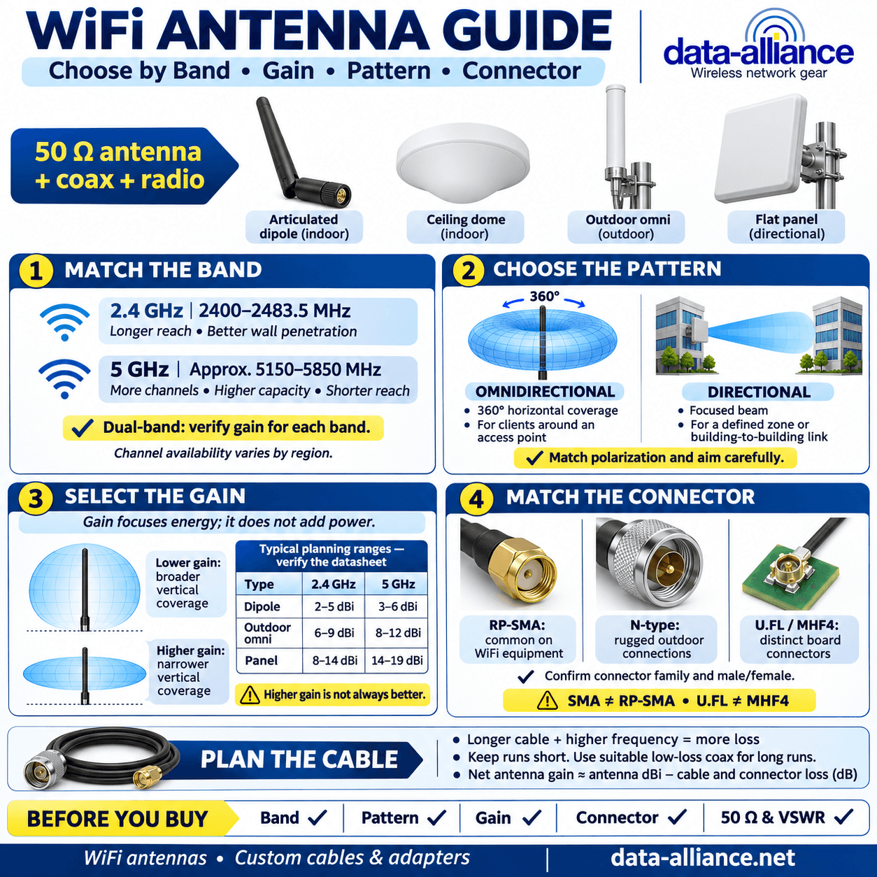
Gain in dBi tells you how an antenna concentrates energy, not how much power it adds. An omnidirectional antenna raises gain by flattening the vertical pattern into a disc; a directional antenna does it by focusing a forward beam. Pick the pattern that matches the geometry of your deployment, then pick the gain that fits the terrain.
Omnidirectional vs directional
- Compact omni (2–3 dBi): typical for end nodes and sensors where the device moves or orientation is unpredictable. Short whip or internal antenna.
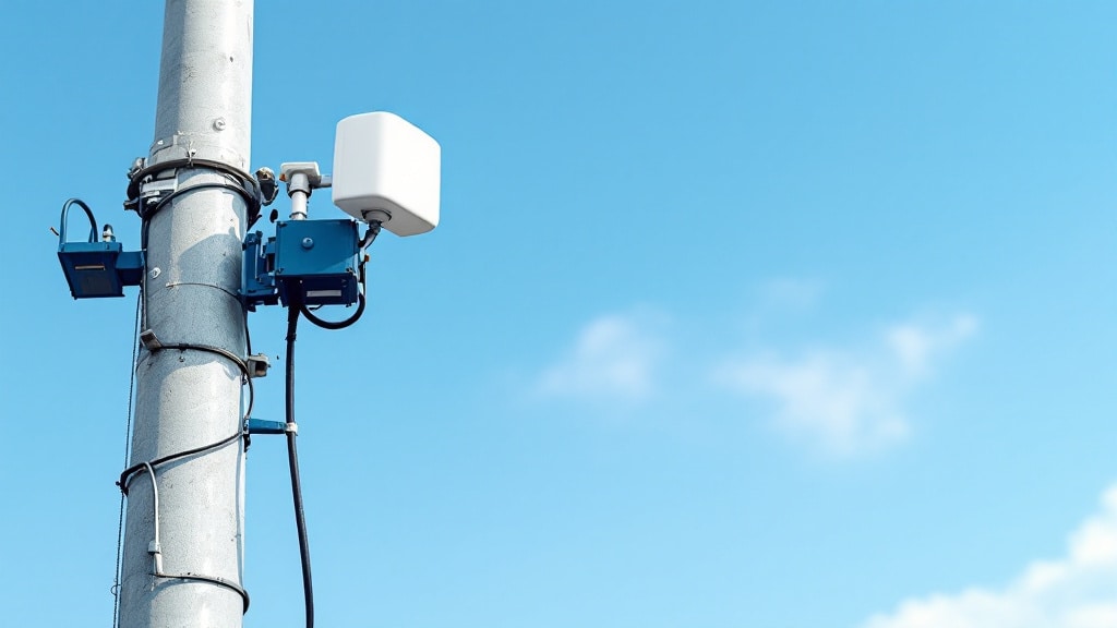
- High-gain omni (5–8 dBi): the workhorse for a gateway that must cover 360° over flat or suburban terrain. Fiberglass collinear antennas are common here.
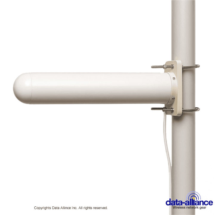
- Directional Yagi (10–15 dBi): for point-to-point backhaul or reaching a single remote cluster. Higher gain narrows the beamwidth, so aiming and mounting rigidity matter. See our Yagi antenna guide for beamwidth and front-to-back trade-offs.
Treat vendor gain figures skeptically. A sub-GHz omni genuinely delivering 8 dBi is physically long; a short "8 dBi" whip is almost certainly overstated. When a spec looks too good for the antenna's size, ask for the radiation pattern or a VSWR plot before you commit.
LoRaWAN antenna connectors and impedance
LoRaWAN hardware is a 50-ohm RF system end to end. Mismatch anywhere raises VSWR and wastes link budget, so the connector family has to match your radio, pigtail and feedline. The common connectors on LoRaWAN nodes and gateways are:
| Connector | Typical use on LoRaWAN gear | Notes |
|---|---|---|
| SMA | Many gateways and external antennas | 50-ohm, threaded; verify male/female gender |
| RP-SMA | Some gateways/modules (reverse polarity) | Looks like SMA but the center pin is reversed — not cross-compatible |
| N-type | Outdoor high-gain and Yagi antennas | Rugged, weatherproof, low loss at sub-GHz |
| U.FL / MHF4 | On-board module connection | Micro-coax; pair with a pigtail to an external bulkhead connector |
SMA and RP-SMA are the single most common source of mismatched orders — they thread together but will not mate correctly. If you are unsure which is which, our ground plane antenna guide is also worth a read for how the mounting surface interacts with a quarter-wave whip's pattern and match. For a full connector-by-connector reference, verify gender and polarity against the datasheet before ordering.
Feedline and cable loss at 900 MHz
Cable loss is subtracted directly from your link budget, and on an outdoor gateway the coax run can erase much of a high-gain antenna's advantage. At roughly 900 MHz, thin RG-174 loses a great deal per foot, while low-loss LMR-400-class coax is dramatically better — which is why a short run of good coax often beats a long run of thin cable even at the same connector. Keep the feedline as short as practical, mount the antenna high, and size the coax to the run length. For specifics and loss-per-100-ft figures by frequency, see our LMR-400 cable selection guide.
Always verify the published loss figure for the specific cable and length at your operating frequency rather than assuming — datasheet loss is quoted per 100 ft at a stated frequency, and 900 MHz loss differs from the headline numbers often quoted at 2.4 GHz.
How to choose: a quick selection flow
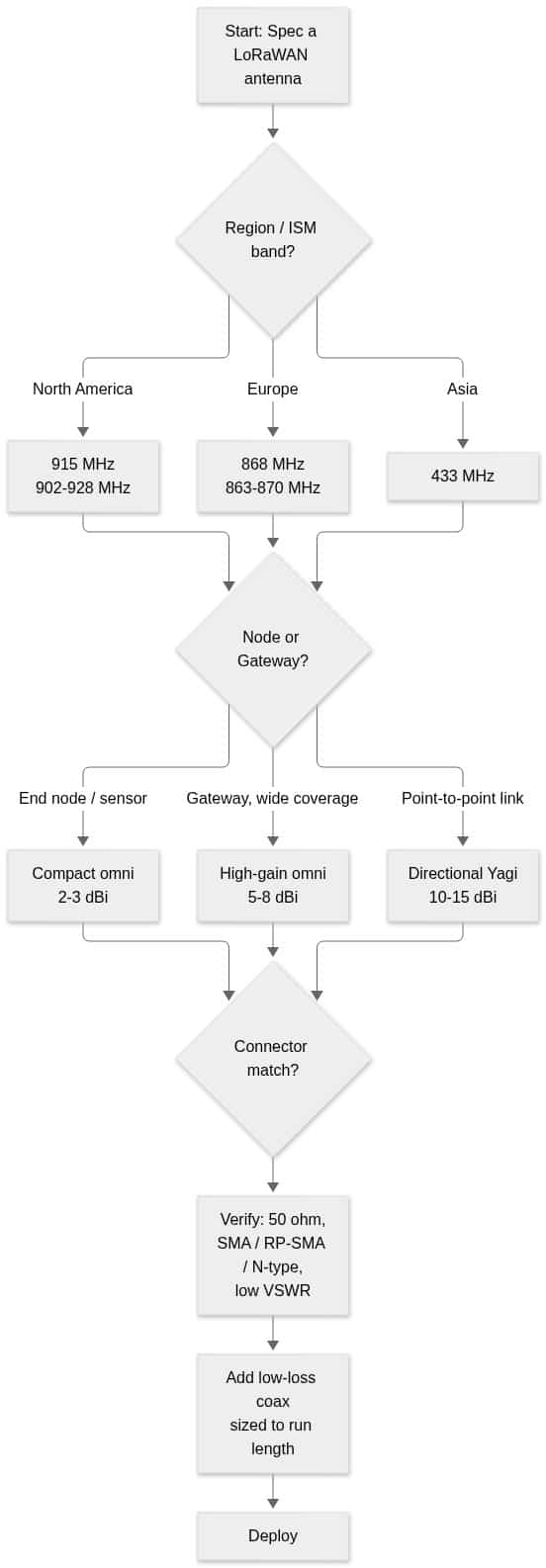
- Region → band. 915 MHz (North America), 868 MHz (Europe), or the correct regional plan.
- Node or gateway? Compact omni for nodes; high-gain omni or directional for gateways and links.
- Pattern → gain. 360° coverage = omni; a known heading = Yagi. Match gain to terrain, not to the highest number on the box.
- Connector. Confirm SMA vs RP-SMA, N-type or U.FL/MHF4, plus gender, against your radio.
- Feedline. 50-ohm, low-loss, as short as the install allows.
Need help matching an antenna to a specific gateway or node? Browse our LoRa / LoRaWAN antennas and custom-built antenna cables and adapters, or request a custom quote and our technical team will spec the band, connector and cable length for your deployment. For a broader primer on antenna fundamentals, the LoRa antenna guide covers gain and pattern in more depth.
Frequently asked questions about LoRaWAN antennas
What frequency should a LoRaWAN antenna be?
Match the antenna to your regional ISM band: 902–928 MHz (915 MHz) in North America, 863–870 MHz (868 MHz) in Europe, and 433 MHz or a regional 920 MHz plan in parts of Asia. Using an antenna tuned to the wrong sub-band raises VSWR and reduces range.
How much gain do I need for a LoRaWAN gateway antenna?
For 360° coverage over flat or suburban terrain, a 5–8 dBi omnidirectional antenna is the common gateway choice. For a point-to-point or long single-heading link, a 10–15 dBi directional Yagi concentrates energy toward the target at the cost of beamwidth. Be skeptical of high gain claimed on a physically short antenna.
Does a higher-gain antenna always give more range?
No. Omnidirectional gain is achieved by flattening the vertical pattern, so a very high-gain omni can shoot over nearby low-lying nodes or struggle on hilly terrain. Gain helps most when the pattern matches your geography — verify the radiation pattern, not just the dBi number.
What connector do LoRaWAN antennas use?
Most external LoRaWAN antennas use SMA or N-type; some modules use RP-SMA or an on-board U.FL/MHF4 connection fed by a pigtail. All are 50-ohm. Confirm the exact connector family, polarity and gender against your radio before ordering — SMA and RP-SMA thread together but do not mate correctly.
How long can the coax cable be between the radio and the LoRaWAN antenna?
As short as the install allows. Cable loss at ~900 MHz is subtracted straight from your link budget, so a long run of thin coax can erase a high-gain antenna's benefit. Use low-loss LMR-400-class coax for longer runs and verify the published loss at 900 MHz for your specific length.