


Antennas, Antenna Cables, Wireless Products: Technical Articles

Ground Plane Antenna Guide: How Ground Planes Set Gain, Pattern & VSWR
A ground plane antenna is a monopole (typically a quarter-wave vertical element) that relies on a conductive surface beneath the feedpoint to act as the electrical "other half" of the antenna. Without that ground plane, a monopole is only half an antenna: the surface reflects the element and completes the RF circuit, and its size, shape and conductivity directly set the antenna's gain, radiation pattern and impedance match. If you have ever bolted a whip to a small plastic bracket and watched VSWR climb and range collapse, you were fighting a missing or undersized ground plane. This guide explains how a ground plane antenna works, how to size it, and how to mount it so it actually performs.

What a ground plane antenna actually is
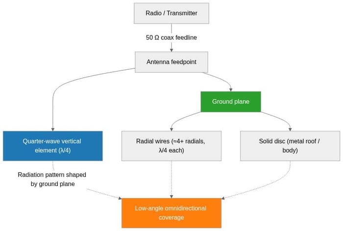
The classic ground plane antenna is a vertical quarter-wave (λ/4) radiating element fed against a horizontal conductive plane. Electrically, the ground plane creates a mirror image of the vertical element, so the monopole behaves like a half-wave dipole with the "missing" lower half supplied by the reflection. That image is what lets a short vertical radiate efficiently and present a usable feedpoint impedance to a 50-ohm radio.
The ground plane can take two common forms:
- Solid disc / sheet — a continuous metal surface such as a vehicle roof, equipment chassis, or a purpose-built disc.
- Radials — three or more (four is typical) quarter-wave wires or rods projecting from the base, approximating a solid plane while cutting weight and wind load.
How the ground plane sets gain, pattern and VSWR
Three antenna behaviors are governed by the ground plane, and they are the reasons a "ground plane antenna" is a category worth understanding rather than an afterthought.
Radiation pattern and takeoff angle
A horizontal ground plane pushes the pattern toward the horizon, giving the low-angle, omnidirectional coverage you want for terrestrial links. Tilting radials downward (a "drooping radial" design, often around 45°) raises the feedpoint impedance closer to 50 ohms and can slightly lift the takeoff angle. A ground plane that is too small or asymmetric distorts the pattern and can tilt the main lobe off-axis.
Feedpoint impedance and VSWR
A quarter-wave monopole over a large, perfect ground plane presents roughly 36 ohms — a modest mismatch to 50-ohm systems. Real ground planes, radial angle, and nearby metal all move that figure. An undersized ground plane raises reactance and pushes VSWR up, wasting transmit power as reflected energy. If you are diagnosing a poor match, our explainer on what VSWR means for your antenna and cable walks through interpreting the numbers and lowering a high reading.
Efficiency
Ground plane conductivity matters. A well-bonded metal roof is an excellent plane; a rusty bracket, a painted-over seam, or a plastic surface is not. Poor bonding shows up as lost efficiency and unstable VSWR that changes when you touch the mount.
Sizing a ground plane antenna: quarter-wave math
The vertical element and each radial are cut to a quarter wavelength for the operating frequency. Use the free-space wavelength and a velocity/end-effect factor (commonly ~0.95 for a thin element) to get a practical starting length, then trim for lowest VSWR. As a reference, the quarter-wave lengths below are approximate physical lengths — always verify against your specific element diameter and a VSWR sweep.
| Band / frequency | Free-space λ | Approx. λ/4 element (≈0.95 factor) | Typical use |
|---|---|---|---|
| 433 MHz (ISM) | ~692 mm | ~164 mm | Sub-GHz IoT, remote control |
| 915 MHz (US ISM / LoRa) | ~328 mm | ~78 mm | LoRa/LoRaWAN, Helium, telemetry |
| 1575.42 MHz (GPS L1) | ~190 mm | ~45 mm | GNSS receive (needs solid ground plane) |
| 2.4 GHz (Wi-Fi/BT) | ~125 mm | ~30 mm | Wi-Fi, Bluetooth, Zigbee |
| 5.5 GHz (Wi-Fi) | ~55 mm | ~13 mm | 5 GHz Wi-Fi, point-to-point |
Figures are rounded starting points, not guaranteed dimensions. Element diameter, coating, and mounting hardware all shift resonance — confirm with a VNA or antenna analyzer before you commit to a build.
Solid ground plane vs radials: which to use
| Approach | Pros | Cons | Best for |
|---|---|---|---|
| Solid disc / metal surface | Predictable pattern, best for high-frequency and GNSS, easy to bond | Heavier, more wind load, size grows at low frequencies | GPS antennas, vehicle roofs, chassis-mount whips |
| Radials (3–4+ elements) | Light, low wind load, practical at HF/sub-GHz | Pattern depends on radial count/angle; more to install | Sub-GHz base stations, LoRa/repeater masts |
| Ground-plane-independent antenna | Works with little or no external plane (built-in counterpoise) | Often lower gain; verify spec, not marketing | Plastic enclosures, small IoT devices, non-metal mounts |
When you have no usable metal surface — a plastic housing, a fiberglass mast, a small sensor node — do not force a ground-plane-dependent whip onto it. Choose a ground-plane-independent antenna (one with an internal counterpoise) instead. Our guidance on antennas mounted on metal enclosures covers the flip side of this problem, where the enclosure itself interacts with the antenna.
Mounting and grounding: getting the plane right in the field
Even a correctly sized ground plane antenna underperforms if it is mounted poorly. A few field rules:
- Center the element on the plane where possible; an off-center feed skews the pattern.
- Bond to bare metal. Scrape paint and corrosion at the mounting point so the plane is electrically continuous with the antenna base.
- Keep radials symmetric and at a consistent angle — asymmetry shows up as a lopsided pattern and drifting VSWR.
- Mind the mount material. The bracket is part of the RF system. See our antenna mount guide for L-brackets, pole, roof and magnetic mounts to match the mount to the surface and grounding you need.
For low-frequency whips and quarter-wave verticals on Wi-Fi and IoT gear, the same quarter-wave principles carry over — our 2.4 GHz antenna guide shows how element length and ground plane interact at that band.
Choosing the right ground plane antenna for your build
If you are matching an antenna and feedline to a ground-plane design, Data Alliance stocks the components and can build custom assemblies to your dimensions. Browse our WiFi antennas for quarter-wave and omnidirectional options, and pair them with custom antenna cables and adapters cut to your connector and length. Not sure the ground plane your platform provides is adequate? Request a custom quote or contact our technical support with your frequency, mounting surface and radio, and we will help you spec the element, radials, and cable before you install.
Frequently asked questions
Does a ground plane antenna need a metal surface to work?
A traditional quarter-wave monopole does — it uses the metal surface (or radials) as its counterpoise. If you have no metal, choose a ground-plane-independent antenna with a built-in counterpoise; forcing a ground-plane-dependent whip onto plastic will raise VSWR and cut range.
How big does the ground plane need to be?
A common rule of thumb is a radius of at least a quarter wavelength in every direction from the element, with larger planes giving a cleaner, lower-angle pattern. At GPS L1 and Wi-Fi frequencies the required disc is small; at sub-GHz LoRa/433 MHz frequencies it becomes large enough that radials are usually more practical.
Why did my VSWR get worse after mounting the antenna?
Almost always the ground plane changed. An undersized, painted, corroded, or asymmetric plane shifts feedpoint impedance and raises VSWR. Bond to bare metal, center the element, keep radials symmetric, and re-sweep. See our VSWR explainer for how to interpret and reduce the reading.
How many radials do I need?
Three will work; four symmetric quarter-wave radials are the common practical choice for a ground plane antenna and give a well-behaved omnidirectional pattern. More radials approach the behavior of a solid disc but add installation effort and wind load.
Are radials or a solid disc better?
A solid disc gives the most predictable pattern and is preferred at high frequencies and for GNSS receive. Radials are lighter and far more practical at low frequencies where a solid plane would be impractically large. Match the approach to your band and mechanical constraints.