


Antennas, Antenna Cables, Wireless Products: Technical Articles

VSWR Explained: What Voltage Standing Wave Ratio Means for Your Antenna and Cable
VSWR (voltage standing wave ratio) is a single number that tells you how well an antenna and its feedline are impedance-matched to the radio driving them. It is expressed as a ratio like 1.5:1, where 1.0:1 is a perfect match and larger numbers mean more of your transmitted power is being reflected back toward the radio instead of radiating. For any RF system built on 50-ohm coax — Wi-Fi, cellular, LoRa, GPS, or point-to-point links — VSWR is the fastest way to judge whether a connector, cable, or antenna is doing its job. This guide explains what VSWR measures, how it relates to return loss and reflected power, and the practical steps to bring a high VSWR back down.
What VSWR actually measures
When a radio sends power down a coaxial cable, that power travels as a forward wave toward the antenna. If the antenna's impedance exactly matches the cable and radio (nominally 50 ohms in most wireless gear, 75 ohms in video/CATV systems), the antenna absorbs and radiates all of it. If there is a mismatch, part of the wave reflects back down the cable. The forward and reflected waves interfere with each other, creating a standing wave pattern of voltage peaks and troughs along the line — hence voltage standing wave ratio.
VSWR is the ratio of the maximum voltage to the minimum voltage on that standing wave. A ratio of 1.0:1 means there is no reflected wave at all: a flat line, a perfect match. As the mismatch worsens, the peaks grow and the troughs deepen, and the ratio climbs.
How VSWR relates to reflected power and return loss
VSWR, reflection coefficient (Γ), and return loss are three ways of describing the same mismatch. They are tied together by fixed math, so a VSWR figure can always be converted to "how much power am I losing to reflection" and to a return-loss value in dB.
- Reflection coefficient (Γ) = (VSWR − 1) / (VSWR + 1). This is the fraction of voltage reflected.
- Reflected power = Γ² expressed as a percentage of forward power.
- Return loss (dB) = −20 × log₁₀(Γ). Higher return loss in dB is better — it means less signal is coming back.
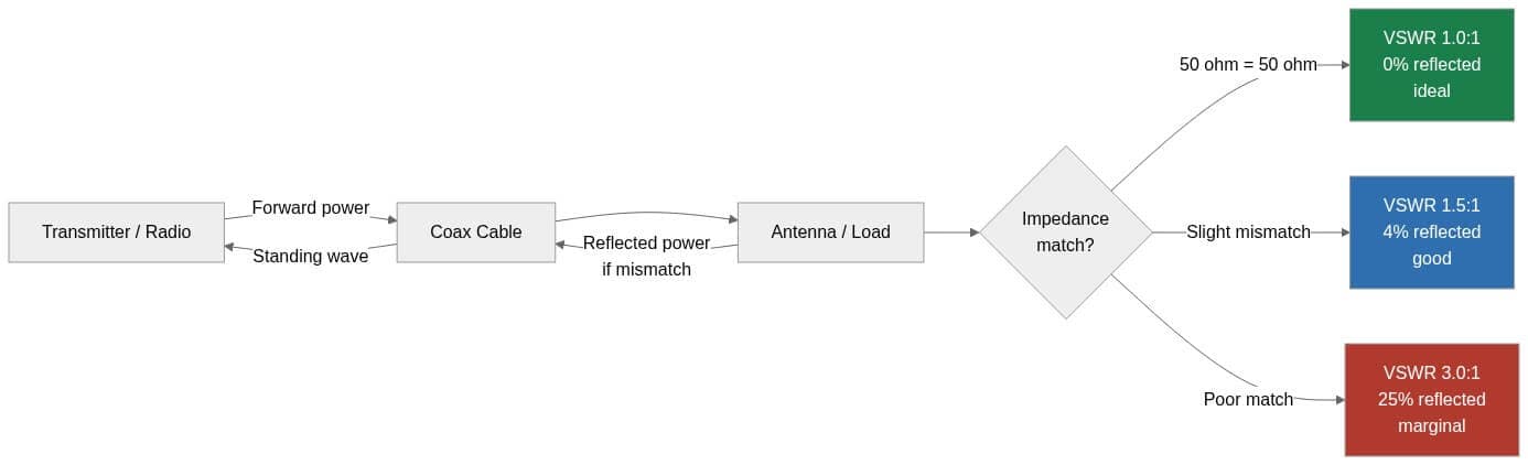
The diagram below shows the basic flow: forward power leaves the radio, a matched load radiates it all, and a mismatch sends a reflected wave back down the coax to form the standing wave.
VSWR chart: ratio, reflected power, and return loss
This reference table maps common VSWR values to the equivalent reflection coefficient, reflected power, and return loss. The figures are derived directly from the formulas above and are exact for a lossless, ideal line — use them as reference targets, not as a substitute for measuring your specific assembly.
| VSWR | Reflection coefficient (Γ) | Reflected power | Return loss (dB) | Practical read |
|---|---|---|---|---|
| 1.0:1 | 0.000 | 0.0% | ∞ | Perfect match (ideal) |
| 1.2:1 | 0.091 | 0.8% | 20.8 dB | Excellent |
| 1.5:1 | 0.200 | 4.0% | 14.0 dB | Good — common spec target |
| 2.0:1 | 0.333 | 11.1% | 9.5 dB | Acceptable for many antennas |
| 2.5:1 | 0.429 | 18.4% | 7.4 dB | Getting marginal |
| 3.0:1 | 0.500 | 25.0% | 6.0 dB | Marginal — investigate |
| 5.0:1 | 0.667 | 44.4% | 3.5 dB | Poor — significant loss/risk |
Note that VSWR describes reflection only. It is not a measure of efficiency or gain — a dummy load can show a beautiful 1.0:1 VSWR while radiating nothing. VSWR tells you power is getting into the antenna, not what happens after that.
What VSWR is good enough? Real-world targets
Acceptable VSWR depends on the system and the transmit power involved. As general guidance for the wireless gear most integrators deploy:
- ≤ 1.5:1 — a common manufacturer spec for quality antennas across their rated band. A good target for fixed installs.
- ≤ 2.0:1 — widely accepted across the operating band for many commercial antennas; only ~11% of power reflected.
- > 2.5:1 to 3.0:1 — worth investigating. On high-power transmitters, sustained reflected power can stress or shut down the PA; many radios fold back power or fault above a threshold.
Always check the antenna's datasheet: VSWR is specified over a frequency band, and a 2.4 GHz antenna forced onto a 5 GHz radio (or a cellular antenna used out-of-band) will show poor VSWR simply because it is out of tune. Verify the antenna is rated for the exact band you are operating.
What drives VSWR up in a real installation
When a bench-perfect antenna measures badly after install, the mismatch is usually introduced between the radio and the radiating element:
- Connector problems — loose, over-torqued, corroded, or poorly terminated connectors are the most common culprit. A single bad crimp or a cross-threaded SMA can wreck an otherwise clean line. Torque SMA connectors to spec rather than hand-tightening blindly.
- Wrong or damaged coax — a kinked, crushed, or water-ingressed cable changes its impedance locally and creates reflections. Cable choice and length also shape how much line loss masks (or reveals) a mismatch.
- Impedance mismatch — mixing 50-ohm and 75-ohm components, or using an adapter that is not a true 50-ohm part, introduces a step the wave reflects off of.
- Out-of-band operation — running an antenna outside its tuned frequency range.
- Nearby metal or detuning — mounting an antenna against a large metal surface or too close to other radiators can shift its resonant point.
A subtle point: because cable loss attenuates the reflected wave on its way back, a long lossy feedline can make VSWR look better at the radio than it truly is at the antenna. Measure at the antenna end when you can, and account for feedline loss. Our antenna cable selection guide walks through matching coax type, connector, and length to your link budget so the feedline itself is not the weak point.
How to measure and lower VSWR
VSWR is measured with a VSWR/SWR meter inline with the feed, or more precisely with a vector network analyzer (VNA), which sweeps the band and plots VSWR (and return loss / S11) across frequency. The related reflection parameter engineers log on a cable assembly is S11 — our breakdown of S11 vs S22 log-magnitude tests shows how return loss is captured at each port of a two-port assembly.
To bring a high VSWR down, work from the radio outward:
- Re-seat and torque every connector; inspect for corrosion and moisture ingress.
- Confirm the antenna is rated for your operating band and is not detuned by nearby metal.
- Swap in a known-good cable to isolate whether the reflection is in the feedline or the antenna.
- Verify all components are the same impedance (50 ohm for most wireless; 75 ohm for video). Avoid low-quality adapters.
- Keep runs as short as practical and use appropriate low-loss coax — for longer outdoor runs, heavier coax like LMR-400 reduces line loss. See our comparison of LMR-100, LMR-200 and LMR-400 for loss figures by band.
Directional antennas such as Yagis are typically specified with a tight VSWR across a narrow band; if you are pushing range on a point-to-point link, our Yagi antenna guide covers how gain, beamwidth, and match interact on a single heading.
Where to get matched hardware
A clean VSWR starts with quality, properly terminated components. Data Alliance custom-manufactures 50-ohm antenna cables and adapters with your choice of coax type, connectors, and length, and stocks WiFi antennas spec'd across their rated bands. Need a specific connector combination or length for a tight match? Request a custom quote or contact our technical support team — we build to spec and ship same day on orders placed before 4pm MST.
Frequently asked questions about VSWR
What is a good VSWR value?
For most wireless installations, 1.5:1 or lower is an excellent, common spec target and 2.0:1 or lower is widely acceptable. At 1.5:1 only about 4% of forward power is reflected; at 2.0:1 it is about 11%. Values above 2.5:1–3.0:1 warrant investigation, especially on high-power transmitters that may fold back power or fault.
What is the difference between VSWR and return loss?
They describe the same mismatch in different units. VSWR is a voltage ratio (e.g., 1.5:1); return loss is the same information in decibels (e.g., 14 dB). Higher return loss in dB means a better match, whereas a lower VSWR number means a better match. A VSWR of 1.5:1 corresponds to about 14 dB return loss.
Does a perfect 1.0:1 VSWR mean my antenna is working well?
Not necessarily. VSWR only tells you power is transferring into the load with minimal reflection — it says nothing about radiation efficiency or gain. A 50-ohm dummy load shows a near-perfect 1.0:1 VSWR while radiating essentially nothing. Use VSWR alongside gain and range checks, not on its own.
Can a long coax cable hide a high VSWR?
Yes. Feedline loss attenuates the reflected wave on its way back to the radio, so VSWR measured at the radio can read better than the true value at the antenna. When accuracy matters, measure at the antenna end or account for the cable's loss in your calculation.
Why does VSWR change with frequency?
Antennas are tuned to resonate over a specific band, so their impedance — and therefore VSWR — varies across frequency. Operating an antenna outside its rated band typically produces a poor VSWR. Always read VSWR against the datasheet's specified frequency range for that antenna.
Is high VSWR dangerous for my radio?
It can be. Reflected power returns to the transmitter's power amplifier, and on high-power gear a sustained high VSWR can cause heating, power fold-back, or a protective fault. Low-power devices are more tolerant, but a persistent high VSWR still means wasted power and degraded performance, so it should be corrected.