


Antennas, Antenna Cables, Wireless Products: Technical Articles
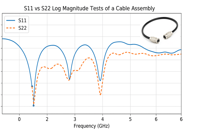
S11 vs S22 Log Magnitude Tests of a Cable Assembly
Understanding S11 and S22 (Reflection Parameters at Each Port)
 S11 vs S22 Log Magnitude Tests of a Cable Assembly
In a two-port RF network (such as a coaxial cable assembly used in IoT, cellular, or GPS systems), S11 and S22 are the reflection S-parameters at port 1 and port 2, respectively. They quantify how much of an incident signal is reflected back at each port due to impedance mismatch.
- S11 measures the return loss looking into port 1 (with port 2 terminated in 50 Ω)
- S22 measures the return loss looking into port 2 (with port 1 terminated)
From a practical Data Alliance support perspective, these parameters help determine how well a cable assembly will integrate with antennas, modems, routers, and RF modules—all of which require consistent 50 Ω impedance.
A well-matched port has minimal reflection (low |S11| or |S22|), while a poorly matched port reflects more energy, reducing system efficiency and potentially degrading signal quality.
Log Magnitude and Return Loss in S-Parameter Tests
Engineers typically evaluate S-parameters in log magnitude (dB):
 This format makes it easier to interpret very small reflections across wide frequency ranges (common in IoT bands up to multi-GHz).
- –20 dB ≈ 1% reflected (excellent match)
- –10 dB ≈ 10% reflected (acceptable in some applications)
Key takeaway for field use:
- More negative dB = better impedance match
- Every additional –6 dB reduces reflected power by ~4×
For Data Alliance customers, this directly impacts:
- Antenna efficiency
- Signal strength (RSSI/RSRP)
- Network stability in LTE/5G and IoT deployments
S11 vs S22: Return Loss at Port 1 vs Port 2
S11 (LogM)
- Specifically tests port 1’s reflection behavior. In practice, to measure S11 of the cable assembly, port 1 of the VNA is connected to one SMP-female end of the cable, and the other end (port 2) is terminated in a known 50 Ω load (often the VNA’s port 2 during a two-port measurement). The S11 reading (in dB) tells us how much signal is reflected back into port 1 versus delivered into the cable. This is effectively the return loss looking into that end of the assembly, encompassing the connector and any discontinuity near port 1. Likewise,
S22 (LogM)
- Is the reflection seen looking into port 2 of the assembly. When measuring S22, the roles are reversed: port 2 is driven and port 1 is the termination. S22 in dB indicates how much of port 2’s incident signal is reflected back toward port 2. In other words, S22 gauges the return loss at the opposite end of the cable (the second SMP-female connector). Together, these two measurements isolate the performance of each end: S11 reveals reflections at the port 1 end, and S22 reveals reflections at the port 2 end. If one end of the cable assembly is less well matched (for example, due to a connector issue or assembly flaw), the corresponding S-parameter (S11 or S22) will show a higher reflection (a less negative dB value) for that end.
Why This Matters in Practice
S11 and S22 isolate each end of the cable assembly.
If one end is degraded (common in field-damaged or poorly assembled cables), you’ll see:
- Higher reflection (less negative dB)
- Frequency-specific anomalies
This is critical when troubleshooting:
- Weak cellular signal
- GPS instability
- High VSWR alarms in RF systems
Symmetry vs. Asymmetry in Cable Assembly Performance
Example S-parameter plots of a coaxial cable assembly (magnitude vs. frequency up to 40 GHz). S11 (top-left) and S22 (bottom-right) both indicate good return loss overall, but a distinct resonance in the S22 curve (~18 GHz) is absent in S11 – highlighting an asymmetry or specific mismatch at port 2.
An ideal coaxial cable assembly is a reciprocal passive network, so we expect it to behave symmetrically from either end. In fact, for a perfect, lossless cable with identical connectors, the reflections at both ends would be the same (S11 = S22 in magnitude). In real-world assemblies, if the construction is truly symmetric and both SMP-female connectors are identical and properly installed, S11 and S22 should be nearly identical traces across frequency. Any significant difference between the S11 and S22 return loss indicates the system is not perfectly symmetrical.
Small S11 vs S22 discrepancies are common and usually traceable to minor physical differences at the two ends. For example, manufacturing tolerances or assembly processes might cause one connector to have a slightly different pin depth or dielectric interface. Even if the cable and connectors are nominally the same, one end could have a subtle impedance bump that the other end does not. Asymmetry in the cable assembly – whether due to a different connector style, a bend in one end, or a slight assembly imperfection – will manifest as S11 ≠ S22. In the example plots above, a pronounced notch (high return loss dip) around 18 GHz appears in S22 but not in S11, signifying a resonance or mismatch specific to the port 2 side. In a truly symmetrical assembly, such a feature would appear identically in both S11 and S22 (or not at all). Thus, engineers interpret differences between S11 and S22 as a diagnostic clue: the end with the poorer return loss or anomalous frequency response is likely the side with a connector or construction issue.
Connector Matching and Assembly Quality Considerations
Connector quality is often the dominant factor in return loss performance—especially in short cable assemblies (e.g., 4-inch RF jumpers).
High-Quality Connector Performance
Well-designed connectors (SMP, SMA, etc.) can achieve:
- ~20–25 dB return loss up to 20 GHz
- Stable impedance transition
Common Assembly Issues
Even small imperfections can degrade performance:
- Air gaps
- Excess solder
- Misaligned center conductor
- Improper crimp or torque
These create impedance discontinuities that show up as:
- Higher reflection
- Frequency-specific dips or spikes
Key Insight for Data Alliance Products
Because many IoT and cellular applications operate at high frequencies:
- Sub-millimeter variations matter
- Consistent assembly processes are critical
Practical Implications of S11 vs S22 Results
1. Connector Mismatch in Real Systems
If:
- S11 = –25 dB
- S22 = –12 dB
Then:
- One end reflects ~0.3%
- The other reflects ~6%
This can cause:
- Signal degradation
- Reduced antenna efficiency
- Increased VSWR at the device
2. Installation Best Practices
If asymmetry exists:
- Connect the better-matched end to the critical device (modem, radio, GPS module)
- Use the weaker end toward less sensitive components
3. Quality Control & Troubleshooting
Differences between S11 and S22 help identify:
- Faulty connectors
- Assembly defects
- Shipping or handling damage
In production and support:
- Both ports must meet spec (e.g., ≤ –15 dB)
- Failure on one end = assembly rejection or rework
4. Impact on IoT & Cellular Systems
Poor return loss can lead to:
- Lower throughput
- Dropped connections
- Reduced range
- Increased power consumption
This is especially critical in:
- LTE/5G routers
- M2M/IoT devices
- GPS timing and tracking systems
5. Measurement Accuracy
In test environments:
- High reflections cause standing waves and ripple
- This introduces measurement uncertainty
For accurate VNA measurements:
- Both S11 and S22 should be low and consistent
6. Port Performance in Systems:
If a cable with an asymmetrical match must be used, system designers might account for it. For instance, the port with higher reflection could be connected to a port that has an isolator or a attenuator pad after it, to buffer the reflection. In test setups, one might calibrate the VNA with the cable in place; the calibration can mathematically null out some cable effects, but a strong mismatch can still re-reflect between the cable and DUT and introduce ripple. Therefore, a high return loss (low reflection) at both ends is especially important for precision measurements (to avoid measurement uncertainty due to multiple reflections).
In Summary
- S11 and S22 measure reflection at each end of a cable assembly
- Log magnitude (dB) expresses return loss clearly and practically
- Matching (low reflection) is essential for RF performance
- Differences between S11 and S22 indicate asymmetry or defects
Data Alliance Best Practice
For reliable RF performance across antennas, cables, and IoT devices:
- Maintain consistent connector quality
- Ensure proper assembly and termination
- Target ≤ –20 dB return loss when possible
- Verify S11 ≈ S22 for symmetry
A well-matched cable assembly ensures that it does not become the limiting factor in system performance—allowing antennas, radios, and IoT devices to operate at their full potential.
FAQs
What do S11 and S22 represent in a two-port RF network?
S11 is the reflection parameter at port 1, and S22 is the reflection parameter at port 2. They quantify how much of the incident signal is reflected back due to impedance mismatch at each port.
How are S11 and S22 related to return loss?
S11 and S22 expressed in dB indicate return loss. A more negative value means less reflection and better impedance matching. For example, –20 dB ≈ 1% reflection, while –10 dB ≈ 10% reflection.
Why do engineers use log magnitude (dB) for S-parameters?
Using 20·log10(|S|) in decibels allows engineers to easily see small reflections over a wide dynamic range. Each –6 dB step corresponds to quartering the reflected power, making performance differences easy to interpret.
How do you measure S11 vs S22 in practice?
To measure S11, port 1 of the VNA connects to the DUT’s port 1 while port 2 is terminated in 50 Ω. To measure S22, the roles are reversed: port 2 is driven and port 1 is terminated.
Why might S11 and S22 differ for the same cable assembly?
Ideally, they should be nearly identical. Differences usually stem from asymmetry: connector mismatches, manufacturing tolerances, or slight assembly imperfections such as pin depth variation or solder gaps.
What are the practical consequences of poor S11 or S22 at one end?
A poorly matched end reflects more power, creating higher VSWR and potential issues for transmitters or sensitive measurement equipment. It also reduces efficiency and measurement accuracy in RF systems.
How do connector quality and assembly affect S11 and S22?
High-quality, properly assembled connectors present close to 50 Ω and yield low reflection (e.g., ≤ –20 dB). Poor assembly (mis-crimp, solder gap, air gap, damaged connector) causes impedance discontinuities, visible as degraded S11 or S22.