


Antennas, Antenna Cables, Wireless Products: Technical Articles
VSWR: Impedance Matching in Antennas & Antenna Cables
Table of Contents
VSWR Explained: Why Impedance Matching Matters in RF Systems
Voltage Standing Wave Ratio (VSWR) is one of the most important indicators of antenna system performance, alongside antenna gain (dBi). VSWR provides insight into how efficiently RF power is transferred from a transmitter, through the antenna cable and connectors, and finally into the antenna itself.
The lower the VSWR, the more efficient the antenna system. A low VSWR indicates that most of the transmitted power is being radiated by the antenna rather than reflected back toward the source.
- VSWR is a measure of the efficiency of connectors).
- VSWR and return loss are two parameters used to determine whether an antenna is effectively impedance-matched internally and to the antenna cable or connectors (line of signal transmission) it is connected to.
- For a radio receiver or transmitter to deliver power to an antenna, the impedance of the radio and the antenna cable should match well with the impedance of an antenna.
- 50 Ohms is the correct impedance for antennas and antenna cables for all of the following applications: WiFi (802.11AC, N, G, A, B), LTE (4G), GSM (3G), ISM, IoT wireless protocols including Bluetooth, RFID, LoRa, NB-IoT, ZigBee, LTE-m. All of Data Alliance's antennas, antenna cables, and adapters are impedance-matched to 50 Ohms.
- Often, there is a bandwidth range that antennas must satisfy and is defined in terms of VSWR.
What Is VSWR?
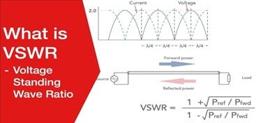
VSWR (Voltage Standing Wave Ratio) measures the efficiency of radio frequency (RF) power transmission from its source, through a transmission line (such as a coaxial cable), to an antenna.
In a perfect RF system, 100% of the RF power would be transmitted through a theoretically loss-less transmission line into the antenna. In real-world systems, however, impedance mismatches between components cause a portion of the RF energy to be reflected back toward the source.
VSWR quantifies this behavior by expressing the ratio between the maximum and minimum voltage along the transmission line caused by reflected waves.
- VSWR = 1.0 : 1 → Perfect impedance match, no reflected power
- VSWR > 1.0 → Increasing levels of mismatch and reflected power
- VSWR → ∞ → Complete impedance mismatch
In most practical RF and wireless communication systems, a VSWR of 2.0 or less is generally considered acceptable for antennas.
VSWR varies from a ratio of 1, indicating a system with no impedance between components, to an absolute mismatch where VSWR is anything up to ∞. A VSWR value of 2 or under is typically acceptable for antennae in communications systems.
The lower the VSWR, the better the antenna impedance matched to the transmission line and the higher the power delivered. Furthermore, a small VSWR reduces reflections from the antenna. 1.0 is the minimum VSWR where no power is reflected, and it’s the ideal condition for an antenna.
Return loss, measured in dB, which indicates how much incident power is reflected in the source of the signal, works in the opposite way from VSWR. The higher the return loss, the more power to an antenna, meaning you are losing less power and signal strength. Low return loss affects the antenna’s capability to radiate, affecting transmission efficiency. For an antenna to have good signal strength and efficient performance, VSWR should be low while dBi should be high.
VSWR related to Antenna Gain (dBi): The dBi value measures an antenna's gain. Antenna gain is a performance metric for the combined performance of an antenna's electrical efficiency and directivity. Depending on the type of antenna (transmitting vs. receiving), gain describes the conversion capability of an antenna, i.e., to convert electrical power into radio waves or radio waves into electrical energy.
For there to be a maximum power transfer (between the transmitter/receiver, the cable, and the antenna), the transmitter/receiver's load impedance must match the cable's impedance. The cable load impedance also has to match the antenna's impedance. If there is a perfect load match, this will result in antenna gain (perfect signal strength and antenna efficiency). Any load mismatches cause a power transfer loss.
Gain is measured in decibels (dB). The dBi value reflects the antenna's directivity and electrical efficiency, differentiating between transmitting and receiving antennae for enhanced characterization of antenna performance.
Impedance-Matching to 50 Ohms
- Impedance is opposition encountered by electrical energy as it moves away from its source.
- Synchronizing load and source impedance will cancel out the effect, leading to maximum power transfer.
- This is known as the maximum power transfer theorem: Maximum power transfer theorem is critical in radio frequency transmission assemblies, particularly in setting RF antennas.
Impedance matching is critical to the efficient functioning of RF setups where you want to move voltage and power optimally. In RF design, the matching of source and load impedances will maximize the transmission of RF power. Antennas will receive maximum or optimal power transfer where their impedance is matched to the output impedance of the transmission source.
50 Ohm impedance is the standard for designing most RF systems and components. The coaxial cable, which underpins the connectivity in various RF applications, has a typical impedance of 50 Ohms. RF research undertaken in the 1920s found that the optimal impedance for the transfer of RF signals would be between 30 and 60 ohms, depending on voltage and power transfer. Having relatively standardized impedance allows for matching cabling and components such as WiFi or Bluetooth antennas, PCBs, and attenuators. Several key antenna types have an impedance of 50 Ohms, including ZigBee, GSM, GPS, and LoRa.
A mismatch in impedance leads to voltage and current reflections. In RF setups, signal power will be reflected back to its source, the proportion being according to the degree of mismatch. This can be characterized using the Voltage Standing Wave Ratio (VSWR), which measures the efficiency of transferring RF power from its source into a load, such as an antenna.
Mismatching between source and load impedances, such as a 75-Ohm antenna and 50-Ohm coax cabling, can be overcome using a range of impedance matching devices, such as resistors in series, transformers, surface-mounted impedance matching pads, or antenna tuners.
In electronics, impedance matching involves creating or altering a circuit, electronic application, or component set so that the impedance of the electrical load matches the impedance of the power or driving source. The circuit is engineered or geared so that the impedances appear the same.
RF Connectors & Coax Cables for IoT Wireless
VSWR performance is not determined by the antenna alone. RF connectors and coaxial cables play a major role in maintaining impedance continuity throughout the signal path.
Poor-quality connectors, incorrect cable types, or improper installations can significantly increase VSWR—even when the antenna itself is well-designed.
For IoT and wireless systems, selecting high-quality 50-ohm coax cables and connectors is essential for maintaining low VSWR, high return loss, and reliable system performance.
Conclusion
VSWR is a critical metric for evaluating antenna efficiency, impedance matching, and overall RF system performance. A low VSWR indicates efficient power transfer, minimal reflections, and optimal antenna operation.
By using properly matched 50-ohm antennas, cables, connectors, and adapters, and by understanding how VSWR relates to return loss and antenna gain, RF designers and installers can ensure reliable, high-performance wireless systems.
When designing or installing RF systems, always aim for:
- Low VSWR
- High return loss
- Appropriate antenna gain
- Consistent 50-ohm impedance throughout the signal path
Related Products: RF Connectors & Coax Cables for IoT Wireless
FAQs
What is VSWR and why is it important in RF systems?
VSWR (Voltage Standing Wave Ratio) measures how efficiently RF power is transferred from a transmitter, through cables and connectors, to an antenna. A low VSWR indicates that most of the transmitted power is being radiated by the antenna rather than reflected back toward the source, resulting in better signal strength, efficiency, and system reliability.
What is considered a good VSWR value for antennas?
A VSWR of 1.0:1 represents a perfect impedance match with no reflected power and is the ideal condition. In practical wireless and RF systems, a VSWR of 2.0 or less is generally considered acceptable and provides good antenna performance with minimal power loss.
How are VSWR and return loss related?
VSWR and return loss describe the same reflection phenomenon using different measurements. VSWR expresses the ratio of reflected voltage to forward voltage, while return loss (measured in dB) indicates how much power is reflected back to the source. A low VSWR corresponds to high return loss, meaning less reflected power and more efficient RF transmission.
Why is 50 ohms the standard impedance for RF antennas and cables?
50 ohms became the industry standard because it offers an optimal balance between power handling and signal loss. Most RF systems—including WiFi, cellular, GPS, and IoT wireless technologies—are designed around 50-ohm impedance. Using matched 50-ohm antennas, cables, and connectors minimizes reflections, lowers VSWR, and maximizes power transfer.
Can cables and connectors affect VSWR performance?
Yes. VSWR performance depends on the entire RF signal path, not just the antenna. Poor-quality connectors, incorrect coaxial cables, impedance mismatches, or improper installation can significantly increase VSWR—even if the antenna itself is well-designed. High-quality 50-ohm coax cables and connectors are essential for maintaining low VSWR and reliable system performance.