


Antennas, Antenna Cables, Wireless Products: Technical Articles
Antenna Radiation Patterns: H-Plane, E-Plane, XY XZ YZ Planes
Table of Contents
Antenna Radiation Patterns:
This article explains antenna radiation patterns, detailing how polarization (linear, vertical, and horizontal) relates to the E-Plane and H-Plane, and how the XY, XZ, and YZ planes correspond to those fields.
What Is an Antenna Radiation Pattern?
A radiation pattern, or antenna pattern, is a graphical representation of how a specific antenna radiates or receives electromagnetic energy in space. Each antenna has a unique radiation pattern, determined by its physical design, electrical properties, and operating frequency.
Radiation patterns are formed by plotting the antenna’s far-field radiation characteristics (the normally radiating field) as charted coordinates, often shown in polar or Cartesian plots.
Antenna patterns are essential for visualizing how an antenna will perform once mounted in its intended orientation. For accurate planning and deployment—especially in wireless networking—radiation patterns must be measured and plotted in the same orientation in which the antenna will be used.
How 3D Radiation Patterns Are Represented in Two Dimensions
Antennas radiate and receive energy in three dimensions. However, visualizing full 3D patterns is impractical for most applications. Instead, antenna patterns are commonly represented as 2D slices through the 3D radiation field, known as principal plane patterns.
These planes intersect at the antenna’s origin and provide a reliable representation of antenna performance when derived from a true 3D dataset.
The Principal Radiation Planes
Azimuth Plane (XY Plane)
Also known as the horizontal plane
Represents radiation around the antenna in a 360° sweep
Elevation Plane (YZ Plane)
Also called the vertical plane
Oriented at right angles to the azimuth plane
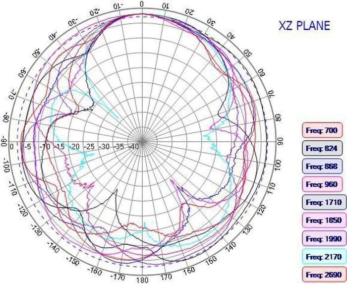
XZ Plane
A third perpendicular plane that also intersects the antenna origin
Provides additional cross-sectional data for pattern verification
These intersecting planes produce complementary radiation plots that, together, describe the antenna’s directional behavior.
Important: For accuracy, these plots should be derived from a true cross-section of a measured or simulated 3D radiation pattern, not independently generated curves.
Linearly Polarized Antennas
Polarization refers to the orientation of the electric (E) field and magnetic (H) field of an electromagnetic wave as it propagates away from an antenna.
In linearly polarized antennas, the electric field oscillates in one fixed plane. The antenna restricts radiation to this single linear direction.
Depending on the antenna’s orientation relative to the earth, linear polarization may be:
Vertical polarization
The electric field oscillates in the vertical plane
Horizontal polarization
The electric field oscillates in the horizontal plane
When interpreting the radiation patterns of linearly polarized antennas, the following planes are used.
The E-Plane (Electric Field Plane)
The E-Plane is defined as:
The plane containing the electric field vector
The direction of maximum radiation
The E-Plane determines whether an antenna is vertically or horizontally polarized.
Vertically polarized antennas
E-Plane coincides with the vertical / YZ / elevation plane
Horizontally polarized antennas
E-Plane coincides with the horizontal / XY / azimuth plane
AZIMUTH PLANE: The Magnetic H plane (or H aperture)
The H-Plane (Magnetic Field Plane)
The H-Plane represents the plane containing the magnetic field component of the electromagnetic wave.
Key characteristics:
Always perpendicular to the E-Plane
Often referred to as the azimuth plane for vertically polarized antennas
Examples:
A vertically polarized antenna
H-Plane coincides with the horizontal (XY) azimuth plane
A horizontally polarized antenna
H-Plane coincides with the vertical (YZ) elevation plane
Radiation Patterns Labeled XY, XZ, and YZ
Radiation patterns may be labeled directly by their Cartesian planes rather than E-Plane or H-Plane terminology.
This applies regardless of whether the antenna is vertically or horizontally polarized.
XY Plane Radiation Pattern
Represents the horizontal (azimuth) radiation pattern
Perpendicular to the E-Plane
Coincides with the H-Plane of a vertically polarized antenna
YZ Plane Radiation Pattern
Represents the vertical (elevation) radiation pattern
Coincides with the E-Plane of a vertically polarized antenna
XZ Plane Radiation Pattern
Provides an additional orthogonal slice
Useful for validating symmetry and side-lobe behavior
Why This Matters in Real-World Antenna Deployment
Understanding how E-Planes, H-Planes, and principal radiation planes relate allows engineers and installers to:
Select antennas with appropriate coverage
Optimize antenna orientation and mounting height
Reduce polarization mismatch losses
Improve link reliability in wireless networks
Summary Table
| Term | Description |
|---|---|
| E-Plane | Plane of electric field and maximum radiation |
| H-Plane | Plane of magnetic field, perpendicular to E-Plane |
| XY Plane | Horizontal / azimuth radiation pattern |
| YZ Plane | Vertical / elevation radiation pattern |
| XZ Plane | Orthogonal validation plane |
| Vertical Polarization | E-Plane in YZ plane |
| Horizontal Polarization | E-Plane in XY plane |
Conclusion
Antenna radiation patterns provide a critical window into how an antenna transmits and receives energy in real-world deployments. By understanding how three-dimensional radiation behavior is represented through principal plane slices—specifically the XY, YZ, and XZ planes—engineers and installers can accurately interpret antenna performance using practical two-dimensional plots.
Equally important is recognizing the relationship between polarization and the E-Plane and H-Plane. The orientation of the electric field determines polarization, while the perpendicular magnetic field defines the complementary plane. Misinterpreting these relationships can lead to incorrect antenna selection, improper mounting orientation, and unnecessary signal loss due to polarization mismatch.
When radiation patterns are correctly measured, labeled, and interpreted in the same orientation as their intended installation, they become a powerful tool for network planning and optimization. A solid grasp of E-Plane, H-Plane, and Cartesian plane representations enables more reliable wireless links, improved coverage, and better overall system performance across a wide range of RF and wireless applications.
FAQs
What is an antenna radiation pattern?
An antenna radiation pattern is a graphical representation of how an antenna radiates or receives electromagnetic energy in space. It shows the relative signal strength in different directions and is determined by the antenna’s design, electrical properties, and operating frequency. Radiation patterns are typically plotted using far-field data in polar or Cartesian formats.
Why are antenna radiation patterns shown in 2D instead of 3D?
Although antennas radiate energy in three dimensions, full 3D patterns are difficult to visualize and interpret. For practical use, radiation patterns are shown as 2D cross-sections—called principal plane patterns—taken from a true 3D dataset. These 2D plots provide accurate insight into antenna performance while remaining easy to analyze.
What are the XY, YZ, and XZ planes in antenna radiation patterns?
- XY Plane: The horizontal or azimuth plane, showing 360° radiation around the antenna
- YZ Plane: The vertical or elevation plane, perpendicular to the XY plane
- XZ Plane: A third orthogonal plane used for additional pattern verification
Together, these planes describe the antenna’s directional behavior.
What is the difference between the E-Plane and H-Plane?
- The E-Plane contains the electric field and the direction of maximum radiation. It determines whether the antenna is vertically or horizontally polarized.
- The H-Plane contains the magnetic field and is always perpendicular to the E-Plane.
Both planes are used to interpret radiation patterns of linearly polarized antennas.
How do E-Plane and H-Plane relate to vertical and horizontal polarization?
- Vertically polarized antennas
- E-Plane: YZ (vertical / elevation plane)
- H-Plane: XY (horizontal / azimuth plane)
- Horizontally polarized antennas
- E-Plane: XY (horizontal / azimuth plane)
- H-Plane: YZ (vertical / elevation plane)
This relationship is essential for correct antenna alignment and system design.
Why is understanding radiation planes important for antenna installation?
Understanding radiation planes helps engineers and installers select the right antenna, orient it correctly, and minimize polarization mismatch. Proper interpretation of E-Plane, H-Plane, and XY/YZ/XZ patterns improves coverage, reduces signal loss, and enhances overall wireless link reliability.