


Antennas, Antenna Cables, Wireless Products: Technical Articles
SMP Connectors & Cable Assemblies — a Practical Guide
Table of Contents
- Introduction
- What is SMP?
- Coax types commonly paired with SMP
- Typical applications
- Design & build notes (to avoid headaches)
- Test & acceptance checklist
- Typical Performance Benchmarks for SMP Cable Assemblies
- Connector choice details that prevent RMAs
- Common SMP assembly mistakes
- Data Alliance: what we supply and technical support
- In summary
- FAQs
Introduction
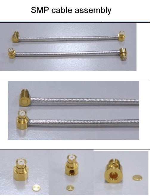
SMP connectors and cable assemblies are a compact, high-frequency interconnect solution designed for dense RF modules and demanding mechanical environments. Commonly used from DC up to 18 or 26.5 GHz—and in precision variants up to 40 GHz—SMP assemblies are ideal where space is limited, blind-mate capability is required, or traditional threaded connectors like SMA are too large or impractical.
In real-world applications, SMP cable assemblies are frequently deployed in high-vibration systems such as vehicles, heavy equipment, aerospace trays, compact radio modules, and embedded GPS/GNSS designs. Their push-on interface, detent retention options, and compatibility with semi-rigid and flexible microwave cables make them especially well suited for rugged, high-density PCB stacks and modular RF architectures.
This practical guide explains what SMP (also known as GPO) is, how it compares to related interfaces, which mechanical and cable variants to choose, what electrical performance to expect, and how to design, specify, and validate SMP cable assemblies for reliable field and lab performance.
SMP cable assemblies are used for:
- High-durability, as needed in high-vibration environments: Examples: Vehicles and heavy machinery. In these situations, they are often for GPS devices or a GPS module embedded in a PCBA or PCB stack.
- High-frequency connections (commonly used from DC to 18/26.5 GHz; precision designs can go higher depending on connector grade and transition design, and even up to 40 GHz for some SMP variants.
What is SMP?
SMP (a.k.a. GPO) is a miniature, push-on RF/microwave connector system designed for high density and blind-mate use. It’s common in compact modules where SMA/SMB are too large or can’t be threaded. SMP uses a gendered plug/jack with spring fingers and a detent to hold engagement.
SMP is part of a family:
SMP (GPO): most common; typical ratings to 26.5–40 GHz (depends on grade).
SMPM (GPPO): smaller; often 40–65 GHz.
SMPS: ultra-mini; specialized, up to ~90 GHz in precision versions.
(This article focuses on SMP/GPO.)
Note: “SMP” is the connector interface family; “GPO” is often used in industry to refer to SMP-compatible connector systems. Always confirm mechanical interface + frequency grade by datasheet.
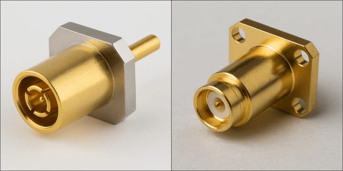
Mechanical variants you’ll encounter
Detent style (retention force):
Full-detent: highest retention; best for shock/vibration; hardest to unplug.
Limited-detent: balance of hold vs. serviceability.
Smooth-bore (no detent): easiest blind-mate; lowest retention (use in captive/bullet applications).
“Bullet” adapters (male–male): enable board-to-board, board-to-chassis, or blind-mate between two SMP jacks. Standard effective lengths let you tune stack-height and float.
Float/guide hardware: many housings allow radial and axial misalignment so modules can mate without precise fixturing.
Launch styles: end-launch and edge-launch PCB jacks; vertical and right-angle; cabled jacks for pigtails; flange/panel versions.
Electrical performance (rule-of-thumb ranges)
Frequency: commercial SMP parts are commonly specified to 26.5 GHz; precision grades and short-transition designs reach ~40 GHz.
Return loss / VSWR: good assemblies often achieve ≥ 15–20 dB RL (≈ VSWR ≤ 1.43:1…1.22:1) over their intended band; premium parts can be better.
Insertion loss: dominated by cable choice and length. The connector adds a small fraction of a dB; short assemblies (e.g., 4 in / 100 mm) are typically very low-loss below 18–26 GHz.
Power handling: modest compared with threaded families; de-rates with frequency and altitude. Think low tens of watts CW at lower GHz on suitable cable—use data sheets for exact curves.
Coax types commonly paired with SMP
SMP is usually mated with semi-rigid or low-loss micro-coax:
Semi-rigid:
0.047″ (RG-178-size inner, copper or CuNi outer): tiny, flexible only when formed.
0.085″ (RG-405) and 0.141″ (RG-402): excellent stability and shielding; you pre-form bends.
Conformable (hand-formable): tinned copper braid/foil jackets that hold a bend, easier than true semi-rigid, slightly higher loss.
Flexible microwave cables: ePTFE or low-density PTFE dielectrics, double-shield braid/foil; chosen when frequent motion or vibration is expected.
Which to pick?
For highest frequency & phase stability: 0.085″ or 0.141″ semi-rigid → SMP.
For service loops / frequent handling: quality flexible microwave cable with SMP crimp/solder jacks.
For tight routing in modules: 0.047″ semi-rigid or micro-flex.
Typical applications
Aerospace/defense RF modules: T/R modules, phased arrays, EW/ radar LRUs—blind-mate trays with bullets are standard.
Satcom & microwave backplanes: dense interconnect where threading is impractical.
Test fixtures & load boards: quick mate/demate, high frequency probing inside enclosures.
5G/mmWave prototypes & compact radios: where board-to-board RF jumpers must be small and repeatable.
- Embedded GPS/GNSS modules in rugged mobile systems
- Compact RF daughtercards in stack-up enclosures
- 5G sub-6 prototypes and compact radios needing dense internal jumpers
- ATE / production test fixtures requiring fast mate/demate
- Aerospace/defense blind-mate trays (you already have this—keep it)
Durability & service life
Mating cycles: commonly 100–500 (varies by finish/detent). Smooth-bore/bullet interfaces tolerate more blind-mate cycles; full-detent retains best but wears faster if over-used.
Materials/finish: bodies in stainless or brass; contacts often beryllium-copper with gold. Keep clean—contamination quickly degrades RL and wear.
Vibration/shock: SMP excels with full-detent or captured bullets in floating housings. For mobile platforms, avoid smooth-bore unless mechanically retained.
Environmental: most variants support –55 °C…+125 °C; check altitude/power for corona limits at high GHz.
SMP cable assemblies — what “good” looks like
For a short (e.g., 4″) assembly:
Return loss (S11/S22): aim ≥ 20 dB across your working band; ≥ 15 dB as a minimum acceptance in many labs. S11 ≈ S22 indicates symmetric build quality.
Insertion loss (S21): small and smooth, rising with frequency; no unexpected ripples or deep notches.
Repeatability: disconnect/reconnect should not shift RL/S21 more than a dB or two at band edges. If it does, check wear/contamination or detent choice.
Design & build notes (to avoid headaches)
Choose detent intentionally.
Lab fixtures: limited-detent for serviceability.
Fielded modules: full-detent + float hardware; use bullets for blind-mate.
Bullet length & float.
Pick bullet length to match your stack height; allow axial float and ±° radial misalignment per the connector’s spec.Cable selection = performance.
Higher diameter → lower loss & better phase stability; trade against bend radius and weight.Termination quality rules return loss.
Control pin depth, dielectric trim, solder/braid prep, and strain relief. Minor geometry errors show up as S11/S22 asymmetry.Routing.
Respect minimum bend radius (typically 5–10× OD for flex; as formed for semi-rigid). Avoid tight bends at the connector heel—use boots or brackets.Cleanliness.
Dust, skin oils, or plating debris raise VSWR. Use lint-free swabs and compatible solvents; cap when not in use.No torque!
SMP is push-on—design mechanical retention if you need it; don’t rely on the RF joint to carry cable loads.
 Test & acceptance checklist
VNA sweep (S11/S22/S21) over the target band; verify both ends meet RL target and traces are smooth.
SWR spot markers at critical bands (GPS, cellular, Wi-Fi, satcom, radar).
Flex test (if applicable): move the cable through expected motion while watching S-parameters for stability.
Mating wear: after N cycles, re-verify RL; inspect springs/fingers for plating wear or splay.
Pros & cons vs. alternatives
Pros
Very compact, high-density, blind-mate capable
High frequency support (well into mmWave in smaller variants)
Supports floating/misalignment with bullets
Cons
Lower power and PIM performance than larger threaded families
Wear and contamination more impactful; finite mating life
No threaded retention—needs proper detent choice and mechanical design
If your application is cellular macro-style with stringent PIM requirements, SMP is usually not the first choice—confirm PIM needs early.
Quick selection guide
Band: up to 18/26.5 GHz → SMP; 40–65 GHz → consider SMPM.
Environment: vibration → full-detent and bullets with float; lab → limited-detent.
Cable: static/precision → semi-rigid 0.085/0.141; service loop/flex → low-loss flexible; ultra-tight space → 0.047″.
Spec targets: design for ≥ 20 dB RL, smooth S21, and adequate power de-rate margin.
Maintainability: cap, clean, and track mating cycles.
Typical Performance Benchmarks for SMP Cable Assemblies
A well-performing SMP cable assembly will show very good return loss on both S11 and S22 across the intended frequency band. Here are some typical benchmarks and acceptable values for high-quality SMP-F cables:
- Return Loss (S11, S22): Aim for at least 15 dB return loss or better across the operating band. In high-performance applications, ≥20 dB is often expected, especially at lower GHz frequencies (20 dB RL corresponds to ~1% reflected power). Many SMP cable connectors can achieve 20–26 dB return loss in practice over a broad range. For example, a certain SMP termination is rated for ~26 dB up to 8 GHz and ~20 dB up to 18 GHz, and a straight SMP cable connector is specified at ≥23 dB up to 20 GHz. These numbers indicate an excellent match (VSWR on the order of 1.1–1.2:1). An assembly hitting around 20 dB RL or above is considered excellent. Around 15 dB (VSWR ~1.43:1) is generally acceptable for many high-frequency systems, but it might be the lower limit for stringent applications. If return loss drops to ~10 dB or worse (≈ 2:1 VSWR), that’s usually a red flag – it means ~10% or more of the power is reflected, pointing to a sub-par connector or a problem in the assembly.
- Symmetry: A good SMP cable assembly should have S11 and S22 that nearly overlap when plotted. In other words, both ends should perform comparably. As noted, any major deviation means one end is not meeting the same benchmark as the other. For a quality cable, you might see both S11 and S22 stay better than –20 dB through, say, 6 GHz, gradually reducing to –15 dB at the top frequency. If one end only manages –15 dB at mid-band while the other is –25 dB, the assembly is not uniformly performing. High-end test cables (including those with SMP or similar connectors) are often characterized by very symmetric S11/S22 curves, indicating uniform construction.
- Insertion Loss (FYI): Although the question focuses on S11/S22, it’s worth noting that a 4″ cable will have very low insertion loss (S21) – perhaps on the order of a few tenths of a dB at high GHz frequencies. This means most signal loss is not due to length but any mismatch at the ends. That puts even more emphasis on return loss: with such a short cable, a poor return loss could actually be the dominant source of signal issue (since little is lost in the cable itself). Thus, meeting the return loss benchmarks is critical for the assembly to be considered “well-performing.”
Data Alliance can provide VNA test results (S-parameters) by request for prototype and validation builds.
Connector choice details that prevent RMAs
A. Straight vs Right-Angle
Right-angle SMP terminations can be convenient, but at higher GHz they’re often more sensitive to routing and strain at the connector heel. If performance is critical, prefer straight SMP and manage cable routing mechanically.
B. Strain relief is not optional
SMP is push-on—do not use the RF interface as the mechanical anchor. Use boots, clamps, brackets, or tie-downs to remove cable load from the connector.
C. Cable heel bend rule
Avoid tight bends within the first 10–20 mm behind the connector (or per cable datasheet). Most RL problems at high GHz show up from heel stress + dielectric deformation.
Common SMP assembly mistakes
- Selecting smooth-bore in vibration without mechanical retention
- Using ultra-small cable for a long run and blaming the connector for loss
- Over-bending at the connector heel
- Skipping caps/cleaning (finger oils → degraded RL)
- Mating cycles exceeded (springs/fingers wear)
- No controlled stack height for bullets in blind-mate designs
- Not specifying detent grade / retention requirement on drawings
Data Alliance: what we supply and technical support
A. “What we need from you to quote/build an SMP cable assembly”
Add this as a boxed checklist:
To quote or build an SMP cable assembly, provide:
- Target frequency band (e.g., DC–6 GHz, DC–18 GHz, DC–26.5 GHz)
- Cable type preference (semi-rigid, conformable, flexible microwave)
- End A / End B connector types (SMP plug/jack + straight/RA + detent type)
- Overall length (and length tolerance if phase matters)
- Minimum bend radius / routing constraints
- Environment (vibration, temperature range, outdoor/indoor)
- Quantity (prototype vs production)
- Any test requirements (VNA plots, RL min spec, insertion loss, phase match)
Data Alliance can build to your drawing (build-to-print) or help you choose the right cable/connector stack for your module.
B. “Selection in 60 seconds”
You already have a quick guide. Make it more scannable and buyer-friendly:
60-second SMP selection
- Vibration / mobile platform: full-detent + strain relief + controlled routing; consider captured bullet + floating hardware
- Blind mate backplane / tray: smooth-bore + bullet + float/guide hardware
- Highest stability / phase critical: 0.085″ or 0.141″ semi-rigid + short transitions
- Frequent handling / service loops: flexible microwave cable + limited-detent
- Ultra-tight packaging: 0.047″ semi-rigid or micro-flex (confirm loss + bend constraints)
How Data Alliance supports SMP projects
- SMP (GPO) connectors and adapters (including bullets where applicable)
- Semi-rigid, conformable, and flexible microwave cable assemblies
- Custom lengths, end styles (straight/RA), detent selection guidance
- Build-to-print or design assistance for blind-mate stackups
- Optional VNA sweep / S-parameter reporting for validation
- Support for connector transitions, routing constraints, and EMI/mechanical strain control
In summary
A well-performing 4″ SMP cable assembly in high-frequency testing would typically show on the order of 20 dB or better return loss on both S11 and S22 across the band of interest, with very little difference between the two ends. Practically, values like “≥20 dB up to 18 GHz” or “≥15 dB up to 40 GHz” might be seen on spec sheets, and technicians often use ~15 dB as a cutoff for acceptable VSWR in many applications. Hitting these marks ensures that reflections are minimal, connectors are well matched, and the cable assembly can be confidently used in demanding RF tests without introducing significant measurement errors or losses.
If you’re selecting SMP detent style, bullet length, or cable type for a high-density module, Data Alliance technical support can help you choose a stack that meets your frequency, routing, and vibration requirements. We can build custom SMP cable assemblies to length and, if needed, provide VNA test results for validation.
FAQs
What is an SMP connector and when should I use it?
SMP (also called GPO) is a miniature, push-on RF connector designed for high-density and blind-mate applications. It’s ideal when space is limited, when threading (like SMA) is impractical, or when modules must mate quickly inside compact RF assemblies such as PCB stacks, GPS modules, and aerospace trays.
What frequency range do SMP cable assemblies support?
Most commercial SMP connectors are rated up to 18 GHz or 26.5 GHz, while precision versions and optimized transitions can support up to 40 GHz. Always confirm the frequency rating and performance grade in the connector’s datasheet.
Which detent style should I choose: full, limited, or smooth-bore?
- Full-detent: Best for high-vibration or shock environments; strongest retention.
- Limited-detent: Easier to disconnect; common in lab or service applications.
- Smooth-bore: Best for blind-mate designs using bullets; lowest retention and should be mechanically captured in vibration environments.
What return loss should a good SMP cable assembly achieve?
A high-quality SMP assembly should typically achieve:
- ≥ 20 dB return loss across the working band (excellent performance)
- ≥ 15 dB as a common minimum acceptance level
S11 and S22 should closely match. Large differences between the two ends may indicate assembly or termination issues.
How much insertion loss should I expect from a short SMP cable?
For a short assembly (around 4 inches / 100 mm), insertion loss is typically only a few tenths of a dB, even at high GHz frequencies. Most loss in short cables is caused by mismatch at the connectors—not by cable length—making good return loss especially important.
What cable types are commonly paired with SMP connectors?
SMP connectors are typically used with:
- 0.085″ or 0.141″ semi-rigid cable for highest stability and lowest loss
- 0.047″ semi-rigid for tight routing in compact modules
- Flexible microwave cable for service loops or frequent motion
- Conformable cable for hand-formable installations
Cable diameter affects loss, phase stability, and bend radius.
How does Data Alliance support SMP cable assembly projects?
Data Alliance supplies SMP connectors, adapters (including bullets), and custom cable assemblies using semi-rigid, conformable, or flexible microwave cable. We can build to print or assist with detent selection, bullet length, and cable choice. Optional VNA test reports (S-parameters) are available for prototype and validation builds to ensure performance meets your frequency and return loss requirements.