Antennas, Antenna Cables, Wireless Products: Technical Articles
Antennas Mounted on Metal Enclosures: Guide for Performance
Table of Contents
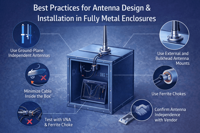
- Best practices for antenna design and installation in fully metal enclosures
- Introduction
- 1. Treat the Enclosure as Part of the Antenna System
- 2. Ensure Consistent Metal-to-Metal Contact (When Required)
- 3. Avoid Inside-the-Box Antennas Unless Using External RF Windows
- 4. Verify Performance Across Feasible Device Orientations
- 5. Consider the Return-Loss Signature as a Diagnostic Tool
- Recommendations for Metal-Enclosed Application
- Why Coax-Radiating Antennas Struggle in a Fully Metal Enclosure
- Key Takeaways
- FAQs
Best practices for antenna design and installation in fully metal enclosures
Introduction
Designing reliable RF systems inside metal enclosures presents unique challenges that are often underestimated. While metal housings provide mechanical strength, environmental protection, and EMI shielding, they also fundamentally alter antenna behavior by acting simultaneously as a ground plane, reflector, shield, and resonant cavity. Small implementation details—such as mounting location, surface coatings, cable routing, or reliance on the coaxial feed line—can dramatically impact antenna tuning, radiation patterns, and real-world performance.
Many antenna issues observed in metal-enclosed systems are not caused by poor antenna specifications, but by unintended interactions between the antenna, the enclosure, and the feed cable. Designs that perform well in open environments or vehicle installations can fail predictably when placed inside a fully sealed metal box that behaves as a Faraday cage. In these cases, antennas that unintentionally depend on the coax shield as part of the radiating structure are especially vulnerable.
This guide outlines practical design principles, diagnostic techniques, and antenna selection strategies for metal-enclosed applications, with a focus on achieving consistent, repeatable RF performance. It explains why certain antenna types struggle in fully metal environments, how to identify problematic designs using VNA measurements, and how to select and install antennas that remain stable regardless of enclosure effects. These recommendations are particularly relevant for industrial equipment, vehicular systems, lockers, cabinets, and IoT devices where metal enclosures are unavoidable and RF reliability is critical.
1. Treat the Enclosure as Part of the Antenna System
A metal housing is effectively a ground plane, reflector, shield, and resonant cavity all at once. Small differences—such as where the through-hole is drilled, whether paint is removed under the antenna base, or how cables are routed—can materially change performance. Always test the antenna in its final mounting location on the actual enclosure, not free-space or a plastic mock-up.
2. Ensure Consistent Metal-to-Metal Contact (When Required)
Some antennas require good electrical coupling to the metal surface to maintain tuning or ground-plane function. If the enclosure is powder-coated or painted, the insulating layer can degrade performance. Ensure bare metal contact where the antenna’s base meets the box—unless the antenna is explicitly designed not to use the enclosure as a ground plane.
3. Avoid Inside-the-Box Antennas Unless Using External RF Windows
Internal antennas only work inside metal enclosures if a deliberate RF-transparent window is added (polycarbonate, fiberglass, acrylic). If no such window exists, performance will be predictably poor regardless of gain or cable routing. Metal blocks nearly all RF above a few MHz.
4. Verify Performance Across Feasible Device Orientations
If the antenna is installed on the top of the enclosure but the entire unit might be mounted vertically, on a pole, or rotated, test performance across all real-world orientations. Metal enclosures often cause asymmetric patterns, so understanding the “strong side” and “weak side” helps avoid installation surprises.
5. Consider the Return-Loss Signature as a Diagnostic Tool
If your VNA sweep shows shifting resonances, new dips, or widening return-loss nulls depending on cable placement or enclosure proximity, the antenna is interacting with its environment in ways that will cause inconsistent performance in the field. A good design shows stable curves regardless of cable layout or locker position.
Recommendations for Metal-Enclosed Application
For enclosed metal boxes with no RF-transparent areas, you will want an antenna solution that does not depend on any part of the cable radiating. Here are some recommendations to ensure reliable performance:
Choose Ground-Plane-Independent Antennas: Look for antennas explicitly designed to be used on metal enclosures or non-metal surfaces without needing the cable as a radiating element. These could be marketed as “through-hole puck antennas with integrated ground plane” or “ground plane independent”. They often have internal counterpoise elements or are constructed as a half-wave radiator. For example, a half-wave dipole (or a 5/8-wave with matching network and ground plane built-in) will be more self-sufficient. Many modern low-profile multi-band antennas for vehicles actually include internal ground planes, which likely makes them suitable for your case – just verify that in the specs or with the vendor.
Use Antennas with External, Through-Hole Mounts and Bulkhead Connectors: In a metal enclosure scenario, ideally the entire antenna element should be outside the box. This usually means mounting the antenna on the exterior (e.g. bolting the puck on the box wall or top) and using a bulkhead connector or a feed-through to get inside. That way, the radiating parts are all outside and not shielded by the box. The cable inside the box then truly serves only as a feed line. If your current antenna was a through-hole puck, ensure it’s installed with a proper metal-to-metal contact as intended (so the box can act as a ground reference if needed). If it was entirely inside, definitely moving it outside is necessary.
Minimize Cable Length Inside the Enclosure: The shorter the cable run inside the metal box, the less chance it can introduce any resonances or issues (and the less loss you incur). If possible, have the cable enter and immediately connect to your radio device or to a connector. Any excess cable should be kept outside or at least not coiled inside the box. Coiling excess cable inside a metal space can also create an inductor/choke effect unintentionally (which might choke signals in some cases). So it’s best to cut cables to needed length (provided the antenna design allows it) or route excess outside.
Use Ferrite Chokes/Isolators at the Feedpoint: As a precautionary measure, you can install a ferrite choke (common-mode choke) on the coax right where it exits the antenna. This will force the antenna to operate on its own by blocking any current on the coax shield. If the antenna’s performance is unaffected by the choke, you know the design is sound for your use. If performance without the choke was relying on the coax, the choke will eliminate that crutch. In a properly chosen antenna, adding a choke simply provides stability and reduces any interference pickup. In your metal locker scenario, the metal enclosure itself is already blocking a lot of coax radiation, but a choke ensures that even as the cable transitions from outside to inside, no unwanted current flows on it.
Test Candidates with VNA and Field Measurements: It sounds like you’re already doing the right thing by VNA-testing antennas with the cable routed inside versus outside. Continue this approach for any candidate antennas. A good antenna for you will show minimal performance difference whether its cable is straight, coiled, inside a box, outside, etc. Its VSWR should remain stable in different cable configurations (again, aside from minor differences due to cable loss). If you find an antenna that meets your frequency/gain needs and passes this test, it’s a strong choice. Additionally, test the whole system in the field (e.g. measure signal strength or throughput with the locker closed vs open) to ensure the antenna is truly performing when the box is closed.
Vendor Guidance and Transparent Specs: Don’t hesitate to ask antenna manufacturers directly whether the cable is a radiating part of the design. While spec sheets may not spell it out, a manufacturer’s applications engineer might confirm if, say, “this antenna requires a 1’×1’ ground plane for rated performance” (implying you should provide one or that the car roof is expected), or if “this antenna is a dipole and doesn’t need the cable to do anything but feed it.” Some antenna makers also provide radiation pattern plots or installation notes that reveal insights. For example, if you see a note like “Ensure a metal ground plane of diameter X under the antenna”, plan to accommodate that (or avoid that model in favor of one that has an internal ground).
Why Coax-Radiating Antennas Struggle in a Fully Metal Enclosure
In typical vehicle installations (e.g. on a truck roof), a few factors help antennas perform: the vehicle’s metal body often provides a ground plane, and there are usually some openings (windows or non-metal areas) that let RF in and out. Many low-profile vehicle antennas are designed to mount on a metal surface, and if they are well-designed, they include internal ground planes or other measures to minimize reliance on the coax. Even if a design unintentionally uses some of the coax for tuning, the cable routing in a vehicle is usually not completely shielded – a portion of the coax might be under the headliner or dash (i.e. within a semi-open cabin), allowing any coax radiation to leak into the environment. A stainless-steel enclosure is a full Faraday cage. Any part of the antenna or cable that sits inside that metal enclosure is effectively isolated from the outside world’s RF environment. This means: if an antenna needs the feed line to radiate or tune properly, and that feed line is mostly inside a metal box, its ability to do so is nullified. The result is exactly what you saw with the VNA and performance tests – significant degradation when the cable was routed inside the enclosure, because the antenna lost whatever “assist” it was getting from the cable acting as an extension of the antenna.
Key Takeaways
Mounting antennas on metal enclosures is fully achievable—but only when the antenna is designed to operate independently of the feed cable and is installed in a way that preserves proper radiation conditions. The most common cause of poor performance in these systems is unintentionally relying on the coax shield as part of the antenna. In a fully metal enclosure, that path disappears, causing the antenna to detune or severely underperform.
To ensure reliable, repeatable performance:
Use ground-plane-independent or dipole-type antennas that do not depend on the coax to radiate.
Mount the antenna externally using proper through-hole or bulkhead feedthroughs.
Minimize cable inside the enclosure and avoid coils or excess length.
Use ferrite chokes to eliminate unwanted common-mode currents.
Validate performance with VNA and real-world signal measurements before scaling deployment.
Engage with vendors to confirm whether the antenna is truly independent of the feed line for tuning and radiation.
In essence, the goal is simple:
Keep the coaxial cable a feed line—not a radiating element—and use an antenna engineered to do all of the radiating itself.
Adopting these practices ensures consistent RF performance, minimizes field failures, and yields a robust design suitable for industrial, vehicular, and IoT environments where metal enclosures are unavoidable.
FAQs
Why do antennas behave differently when installed on or inside metal enclosures?
Metal enclosures significantly alter antenna behavior because they act simultaneously as a ground plane, reflector, shield, and resonant cavity. These effects can detune the antenna, distort radiation patterns, and reduce efficiency. Small details—such as mounting location, surface coatings, or cable routing—can therefore cause large and sometimes unpredictable performance changes.
Can an antenna be installed inside a fully metal enclosure and still perform well?
In most cases, no. A fully metal enclosure functions as a Faraday cage, blocking nearly all RF energy. Internal antennas will only work if the enclosure includes a deliberate RF-transparent window (such as polycarbonate, fiberglass, or acrylic). Without such a window, antenna performance will be severely degraded regardless of antenna gain or cable routing.
Why is metal-to-metal contact important for some antenna installations?
Many antennas rely on the enclosure to act as a ground plane or reference conductor. If the enclosure is painted or powder-coated, the insulating layer can prevent proper electrical coupling, leading to detuning and reduced performance. In these cases, ensuring bare metal contact at the antenna mounting point is critical—unless the antenna is explicitly designed to be ground-plane independent.
Why do antennas that rely on the coax cable struggle in metal enclosures?
Some antenna designs unintentionally use the coax shield as part of the radiating structure. In open or vehicle environments, this may work because the cable is partially exposed to free space. Inside a fully metal enclosure, however, the coax is shielded from the external RF environment, eliminating this unintended radiation path and causing the antenna to detune or underperform dramatically.
How can a VNA be used to diagnose antenna problems in metal enclosures?
A Vector Network Analyzer (VNA) can reveal whether an antenna is interacting poorly with its environment. Shifting resonant frequencies, unstable return-loss curves, or sensitivity to cable routing are indicators that the antenna is affected by the enclosure or coax. A robust design will show stable VSWR and return-loss measurements regardless of cable placement or enclosure orientation.
What type of antenna is best suited for fully metal enclosures?
The best choice is a ground-plane-independent antenna or a dipole-type design that does not rely on the coax cable to radiate. These antennas often include internal counterpoise elements or integrated ground planes and are typically mounted externally using through-hole or bulkhead feedthroughs. This ensures that all radiating elements are outside the enclosure and that the coax serves only as a feed line.