


Antennas, Antenna Cables, Wireless Products: Technical Articles
Antenna Designs That Rely on Coax Cable as Radiator: Avoid
Table of Contents
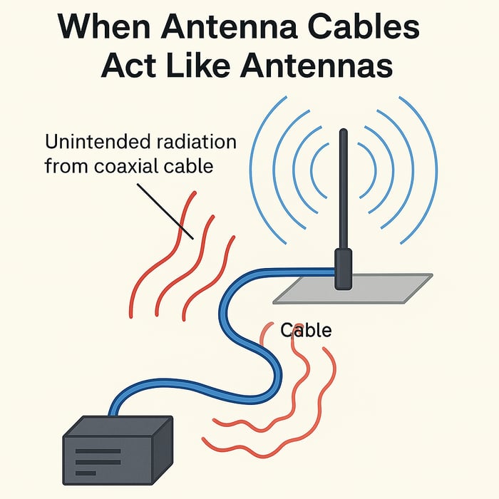
Background: When Antenna Cables Act Like Antennas
Coaxial cables are supposed to be passive feed lines – carrying RF signals between equipment and antennas without radiating energy on their own. In an ideal scenario, all the RF current flows in the cable’s inner conductor, with equal and opposite return current on the inside of the shield, so the fields cancel and no energy is radiated from the coax. However, under certain conditions, a coax cable can start behaving like an antenna itself. This usually happens when there’s an imbalance or flaw in the system that causes RF current to flow on the outside of the coax shield (so-called common-mode current) instead of being confined inside. When that occurs, energy will radiate from the coax and even alter the overall antenna radiation pattern.
In short, a cable that radiates is usually a symptom of an imperfect antenna system, not something we want to happen. Good RF engineering practice aims to keep the cable “just a cable,” not a radiating element.
Antenna Designs That Use the Cable as Part of the Radiator
While coax radiation is often unintentional, some antenna designs effectively rely on the feed cable as part of the antenna – either by necessity or by design compromise. A classic example is a simple quarter-wave monopole (like many “puck” or vehicle antennas): it’s essentially one-quarter-wavelength whip that normally needs a conductive ground plane (or radials) to serve as the other half of the antenna. If no adequate ground plane is present, the antenna will often “recruit” the coax shield as the missing counterpoise. In other words, the antenna tries to use the outside of the coax to complete the RF return path and help radiate.
This phenomenon is well documented in RF literature. As one technical discussion puts it: for electrically short or ground-plane-dependent antennas, the coaxial feedline can become part of the radiating system if a proper counterpoise isn’t provided. In fact, the measured “good” SWR of some compact antennas can be misleading – the low SWR may come from the combined system of the small antenna plus several feet of coax acting as an unintended radiator. If you were to put a proper RF choke on the cable (or otherwise isolate the coax), such an antenna might suddenly stop working or the SWR would shoot up, because the antenna by itself wasn’t doing all the radiating – the cable was doing some of it. This is essentially what you observed in your tests: when the excess cable was tucked inside the metal enclosure (effectively preventing it from radiating), the antenna’s performance dropped off significantly, indicating the design likely depended on that cable radiation.
Real-world product examples exist. For instance, some compact VHF/GPS or AIS “puck” antennas explicitly require a certain length of coax and use it as a makeshift ground plane. One marine AIS antenna’s documentation even stated that the entire 20 m coax “acts as the ground plane” for the antenna, warning users not to shorten the cable. In such designs, the manufacturer is essentially using the feed line as part of the antenna circuit. This kind of design may be a necessary compromise for certain form factors, but it’s obviously not ideal in a fully enclosed metal environment like your lockers.
How to Identify Antennas That Rely on Cable Radiation
Identifying whether an antenna uses the cable as part of its radiating system can be tricky, since vendors rarely advertise this outright. However, there are several clues and methods you can use:
Check the Antenna’s Spec Sheet and Design Type: If the datasheet or product description mentions “requires ground plane” or was tested on a large ground plane (e.g. “performance measured on a 30 cm × 30 cm ground plane”), that’s a sign the antenna is a monopole needing a counterpoise. In the absence of a proper ground plane, such an antenna will likely try to use the coax shield as the counterpoise. By contrast, antennas marketed as “no ground plane (NGP) required” or “ground-plane independent” are designed to not need the vehicle chassis or cable for resonance – they usually have two elements (making a dipole) or an internal ground reference. (Do note: in some CB antenna contexts “NGP kits” simply hide the counterpoise in a special coax setup – but for higher-frequency puck antennas, NGP usually implies a true self-contained design.)
Look for Integrated Ground Plane or Dipole Designs: Many high-quality combo puck antennas include an internal metal ground plane disk or other shielding at the base data-alliance.net. This is a good sign – it means the manufacturer has built in a counterpoise so the antenna can operate standalone. For example, Data Alliance notes that in their multi-element puck antennas, “ground planes are integrated into the antenna design as a metal shield at the base of the antenna.” An antenna with an integrated ground plane or a dipole structure is less likely to depend on the coax for radiation. Conversely, a simple single-element whip coming out of a puck, especially if it’s a quarter-wave length, is more suspect unless the mounting base (or internal circuit) clearly provides a ground.
Fixed Cable Length Requirements: If an antenna comes with a fixed-length cable that the vendor says not to shorten, or if they specify that the cable is part of the tuned system (as in the earlier example, that’s a red flag. This implies the antenna’s resonance/impedance depends on that particular cable length – often meaning the cable is acting as a tuned element. For optimal flexibility, you’d prefer an antenna that can use any appropriate cable length without performance change (aside from normal loss).
Empirical Test – Use of a RF Choke or Common-Mode Filter: One practical way to tell if an antenna is using the coax as a radiator is to isolate the coax and see if performance changes. For instance, you can attach a ferrite choke (common-mode choke) near the antenna feed point to suppress any RF current on the outside of the cable. If the antenna’s SWR or signal strength dramatically changes when you add the choke, it indicates the feedline was indeed carrying significant current (i.e. it was part of the antenna system). A well-designed antenna shouldn’t be that sensitive to adding a choke – ideally it would perform the same, whereas an antenna that needed the coax will “seem to stop working” when the choke blocks the coax’s contribution. In your case, routing the cable inside a metal enclosure works similarly to a choke by killing off external radiation, and the fact that you saw a big performance drop reinforces the conclusion that the antenna was relying on cable radiation.
Lab Tools: If available, more direct measurements can help. Using a clamp-on RF current probe on the coax can detect common-mode current on the shield. Similarly, a near-field RF sniffing probe moved along the cable can reveal if the cable is emitting RF fields. Unintended peaks in an SWR or return loss sweep might also hint that portions of the feedline are acting as resonant radiators. These are more advanced diagnostic methods, but they can confirm whether a cable is “quiet” or radiating.
In summary, antennas that purely use the cable only to transfer signal will not be sensitive to cable length (beyond normal loss) and will specify a feedline just as an accessory. Antennas that implicitly rely on the cable often come with warnings or specific installation notes, or belong to design types known to need a ground/counterpoise. When in doubt, reach out to the manufacturer’s technical support – in some cases they might confirm if the antenna is ground-plane dependent or if there are best practices for cable routing.
Ultimately, the goal is to pick an antenna that will operate efficiently with the cable being just a cable – delivering RF power to the antenna element and not acting as an antenna itself. By using a design that has its own proper ground or counterpoise, you eliminate the “paradox” of needing an exposed cable. This will give you more consistent performance, reduce the risk of interference issues, and align with best practices (keeping the coaxial energy confined to the cable until it reaches the actual antenna).
Conclusion: Keep the Cable as a Cable, Choose a Better Antenna Design
In summary: Some antennas (especially certain compact “puck” styles) do rely on the coax as part of their radiating system, even if unintentionally. Identifying those designs involves looking for signs of ground-plane dependence or performing tests like you have. For a fully metal-enclosed application, it’s crucial to select an antenna designed to be independent of its coax for radiation. That means favoring models with built-in ground planes or dipole configurations, and mounting them externally on your metal enclosure.
By doing so, you ensure that when the enclosure is closed, the antenna itself is doing all the work to send and receive RF signals, and you’re not losing performance because a “hidden” part of the system (the cable) got cut off by the metal walls. This approach, combined with proper installation and perhaps using ferrite chokes as insurance, will give you the best results. The key takeaway is exactly what George’s article drives home: keep the antenna cable as a passive cable, and let a properly engineered antenna handle the RF. This will avoid the quirky situation of an antenna that only shines when its feed line is oddly exposed.
FAQs
Why do coaxial cables sometimes act like antennas?
Coax cables are designed to carry RF signals without radiating, but they can start behaving like antennas when common-mode current flows on the outside of the shield. This usually happens when the antenna system is unbalanced or lacks a proper ground/counterpoise. In that case, part of the RF energy escapes and the coax becomes an unintended radiator, altering the antenna’s performance and radiation pattern.
Do some antennas intentionally use the coax cable as part of the radiator?
Yes. Certain compact or ground-plane-dependent antennas—such as small quarter-wave monopole “puck” antennas—may rely on the coax shield as a substitute counterpoise if no adequate ground plane is present. Some manufacturers even specify a required cable length because the cable is part of the tuned radiating system. While this can work in open environments, it becomes a major performance issue inside metal enclosures where the cable can’t radiate.
What are signs that an antenna depends on cable radiation to function?
Key indicators include:
- Datasheets mentioning “requires ground plane” or testing on a metal ground plate.
- Designs without an internal ground plane or dipole structure—especially simple quarter-wave elements.
- Antennas with a fixed, non-shortenable cable specified as part of the system.
- Performance changing dramatically when a ferrite choke is added or when the cable is routed inside a metal enclosure.
These clues suggest the coax is carrying radiating RF current, meaning the antenna isn’t fully self-contained.
How can I test whether my antenna is using the coax as part of the radiator?
A practical test is to add a common-mode choke (ferrite) near the antenna feed point. If SWR or signal strength drops significantly, the feedline was contributing to radiation. Alternatively, placing the excess coax inside a metal enclosure or using RF current probes can reveal whether the cable is radiating. A well-designed, ground-plane-independent antenna will show little or no change during these tests.
How do I choose an antenna that does not rely on cable radiation?
Select antennas that are explicitly ground-plane-independent or that include an integrated ground plane or dipole structure. High-quality puck antennas often include an internal metal ground plane at the base, preventing reliance on the coax. These antennas maintain proper performance regardless of reasonable cable length, and they’re suitable for fully enclosed metal environments, where the cable cannot radiate. The goal is to keep the cable a passive feedline and let the antenna do all the radiating work.