


Antennas, Antenna Cables, Wireless Products: Technical Articles
Antenna Cable Guide: Coax Types, Loss, Connectors & How to Choose
An antenna cable is the coaxial feedline that carries the RF signal between your radio (or access point, router, or receiver) and the antenna. For almost every wireless system it is a 50-ohm coax assembly, and the one thing that matters most when you choose one is this: the longer the run and the higher the frequency, the more signal you lose in the cable. Pick an antenna cable that is too thin or too long and you can give back every dB of gain your antenna provides. This guide covers the coax types, loss figures, connectors, and impedance rules you need to spec the right assembly.
What an antenna cable actually does
An antenna cable is a coaxial transmission line: a center conductor, a dielectric, a shield (braid and/or foil), and an outer jacket. Its job is to move RF energy from one point to another with minimal loss and without picking up or radiating interference. Two electrical properties dominate the choice of an antenna cable:
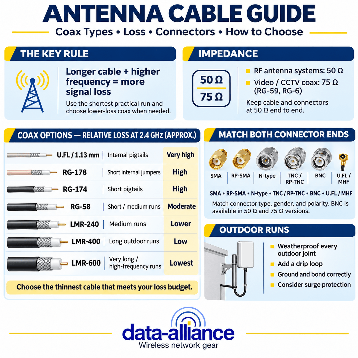
- Characteristic impedance. RF antenna systems are almost universally 50 ohms. Video, CCTV, and broadcast TV coax is 75 ohms (RG-59, RG-6). Mixing the two causes an impedance mismatch, reflected power, and higher VSWR, so confirm 50-ohm coax and 50-ohm connectors end to end.
- Insertion loss (attenuation). Measured in dB per 100 ft (or per 100 m), and it rises with frequency. A cable that loses 2 dB at 400 MHz may lose 6+ dB at 5.8 GHz over the same length.
Antenna cable types: thin flexible coax to low-loss LMR
Coax families trade flexibility and size against loss. Thin cable is easy to route inside an enclosure but bleeds signal over distance; thick low-loss cable preserves signal over long runs but is stiff and needs a larger bend radius. The table below gives approximate 50-ohm loss figures to compare families — always verify the exact attenuation against the specific cable's datasheet for your frequency, as published values vary by manufacturer and construction.
| Coax type | Approx. OD | Typical use | Relative loss @ 2.4 GHz |
|---|---|---|---|
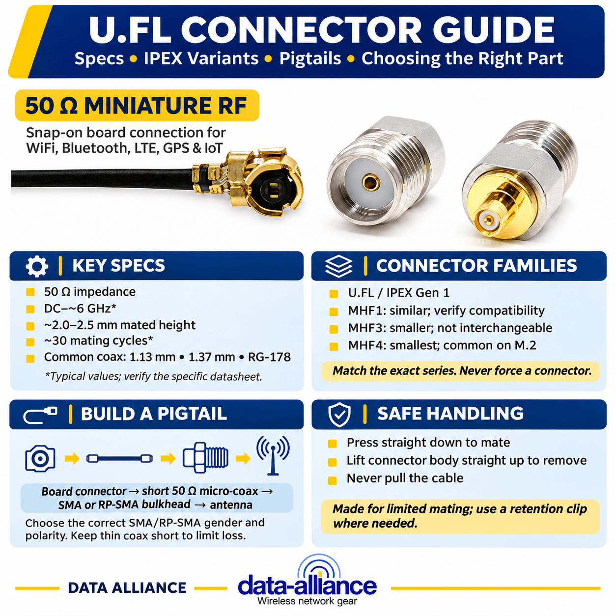
| U.FL / 1.13 mm | ~1.13 mm | Internal PCB-to-antenna pigtails | Very high — keep short |
| RG-178 | ~1.8 mm | Short internal jumpers | High |
| RG-174 | ~2.8 mm | Short pigtails, patch leads | High |
| RG-58 | ~5.0 mm | General-purpose short/medium runs | Moderate |
| LMR-240 (equiv.) | ~6.1 mm | Medium runs, flexible | Lower |
| LMR-400 (equiv.) | ~10.3 mm | Long outdoor runs, low loss | Low |
| LMR-600 (equiv.) | ~14.9 mm | Very long runs / high frequency | Lowest |
Rule of thumb: use the thinnest cable that still delivers acceptable loss for your run length and frequency. For a 30 cm pigtail inside a radio enclosure, RG-174 or 1.13 mm is fine. For a 15 m rooftop run at 2.4 GHz, you want a low-loss LMR-400 cable assembly or better, or the feedline loss will swallow your antenna gain.
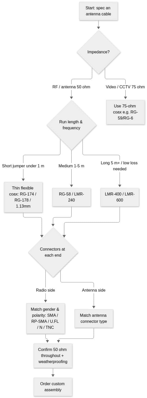
How to choose an antenna cable: a decision flow
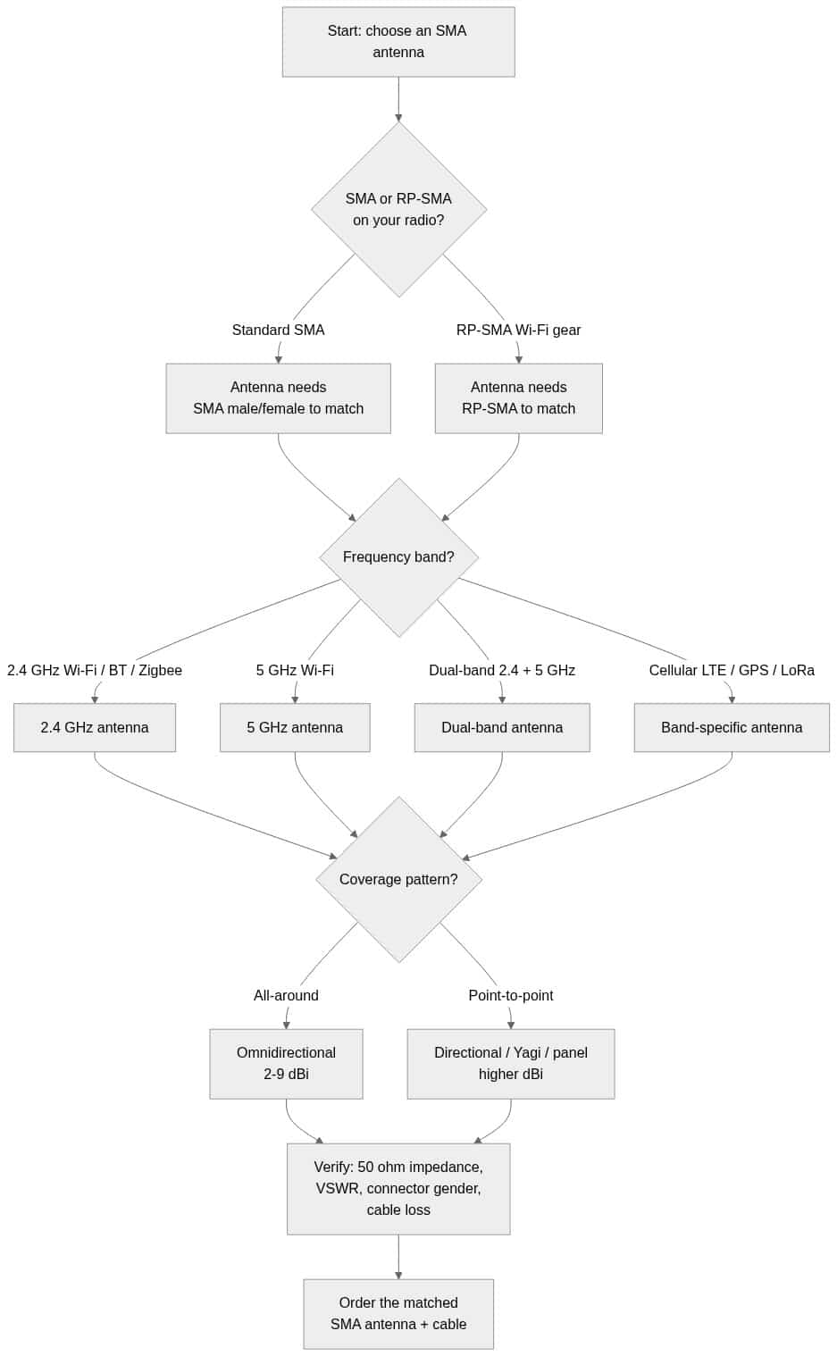
Match four things and the choice falls out: impedance (50 ohm for RF), run length and frequency (which set the coax family), and the connector at each end. The flowchart below walks the decision.
Connectors: matching both ends of the antenna cable
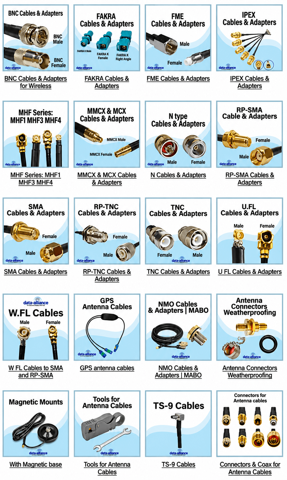
An antenna cable is only as good as its terminations. Every connector interface adds a small amount of loss and is a potential failure point, so you want the minimum number of connectors and the right type and gender at each end. Common 50-ohm RF connectors on antenna cables include SMA and RP-SMA, N-type, TNC/RP-TNC, BNC, and the miniature U.FL/MHF series. Three mistakes to avoid:
- Gender and polarity. SMA and RP-SMA look similar but are not interchangeable — RP-SMA swaps the center pin/socket. Confirm male vs female and standard vs reverse-polarity. Our SMA and RP-SMA antenna guide breaks down the gender rules.
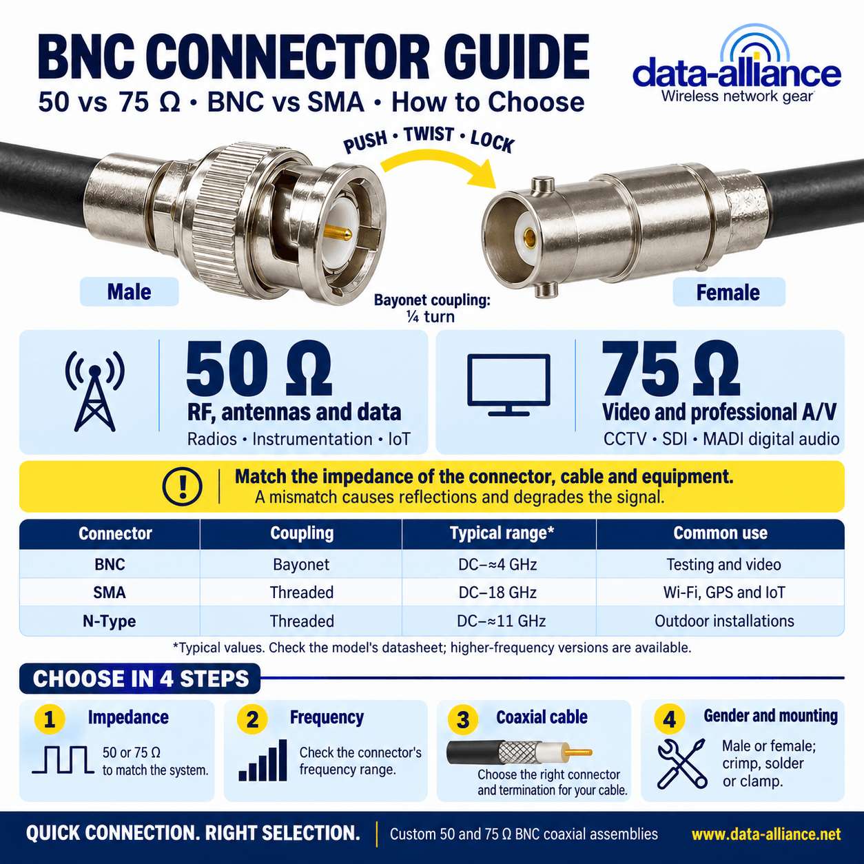
- Impedance at the connector. Most BNC connectors exist in both 50-ohm and 75-ohm versions; use the 50-ohm variant for RF. See the BNC connector guide for the 50 vs 75 ohm distinction.
- Interface selection. N-type is the workhorse for outdoor and higher-power runs; SMA for compact radios; U.FL for internal PCB connections. If you are unsure which interface your hardware uses, the antenna connector types guide maps them all out.
Why cable loss matters more than antenna gain
It is tempting to buy a higher-gain antenna to fix weak signal, but if the feedline is lossy you are paying twice: loss on transmit and loss on receive. The practical move is to keep the antenna cable as short as the installation allows, step up to lower-loss coax before you add antenna gain, and mount the radio close to the antenna when you can. A system budget should account for every dB — antenna gain minus connector loss minus cable loss equals effective radiated performance.
When you need a custom length with specific connectors on each end, order a custom antenna cable assembly rather than chaining adapters — each extra adapter adds loss and a weather point. Pair it with the right WiFi antenna for your band and you have a matched system. Request a custom quote if you need a non-standard length or connector combination.
Outdoor antenna cable: weatherproofing and grounding
Any antenna cable that runs outdoors or terminates at an outdoor connection needs protection. Use connectors rated for the environment, weatherproof every outdoor junction (self-amalgamating tape over the connector is standard practice), and keep drip loops so water runs away from the connector rather than into it. For masts and towers, follow proper grounding and bonding practice and consider inline surge/lightning protection on the feedline where it enters the building.
Frequently asked questions
Is an antenna cable 50 ohm or 75 ohm?
For wireless/RF antenna systems — WiFi, cellular/LTE, GPS, LoRa, two-way radio — use 50-ohm coax and 50-ohm connectors throughout. 75-ohm coax (RG-59, RG-6) is for video, CCTV and broadcast TV. Mixing impedances creates reflections and raises VSWR.
How much signal does an antenna cable lose?
It depends on the coax type, length and frequency. Loss is specified in dB per 100 ft and rises with frequency, so the same cable loses noticeably more at 5.8 GHz than at 400 MHz. Thin coax like RG-174 loses several times more per unit length than LMR-400. Always check the specific cable's datasheet for the loss figure at your operating frequency and multiply by your run length.
Can I just add adapters to make an antenna cable fit?
You can, but each adapter adds insertion loss and another connection that can loosen or let in moisture. For anything permanent or outdoor, a custom assembly built with the correct connectors on each end is more reliable and lower loss than stacking adapters.
What is the difference between RG-174 and LMR-400?
RG-174 is a thin (~2.8 mm) flexible coax suited to short pigtails and internal jumpers; it has relatively high loss. LMR-400-type cable is a thick (~10.3 mm) low-loss coax for long outdoor runs. Use RG-174 where the run is short and routing is tight, and LMR-400 where you need to preserve signal over distance.
How do I know which connectors my antenna cable needs?
Identify the connector on your radio and the connector on your antenna, including gender and whether it is reverse-polarity (RP-SMA vs SMA). Then order a cable with the matching connector on each end. If you are unsure, our antenna connector types guide shows how to identify each interface.
Spec and order your antenna cable
Choose the coax family by run length and frequency, confirm 50-ohm impedance end to end, and match the connector and gender on both the radio and antenna sides. Then build a custom antenna cable assembly or contact technical support for help speccing a non-standard run.