


Antennas, Antenna Cables, Wireless Products: Technical Articles
U.FL Connector Guide: Specs, IPEX Variants, Pigtails & How to Choose
Table of Contents
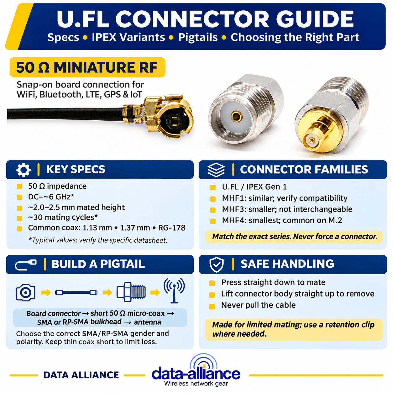
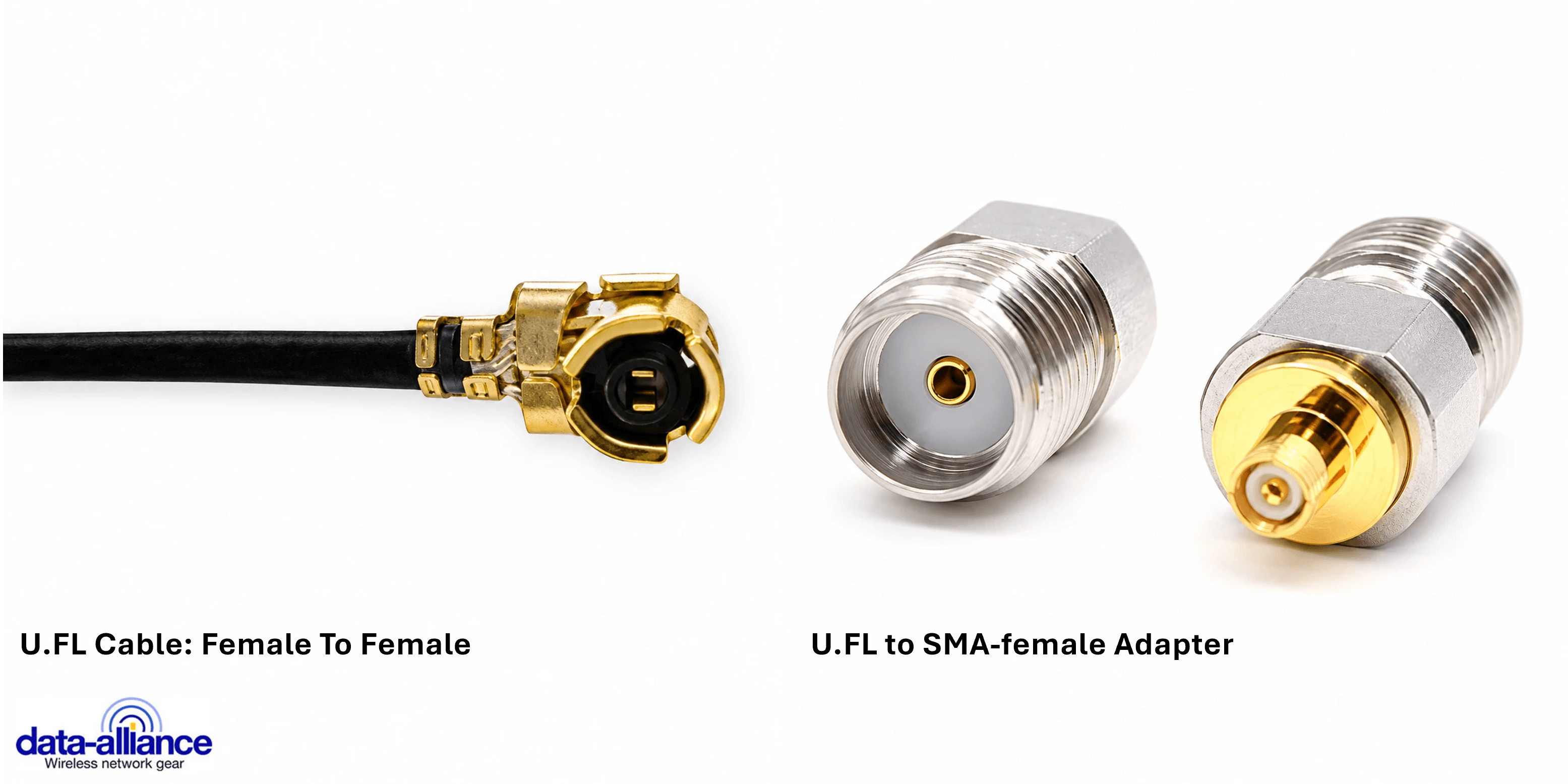
A U.FL connector is a 50-ohm miniature snap-on RF coaxial connector designed for board-level antenna connections on compact PCBs — think WiFi/Bluetooth modules, M.2 and mini-PCIe cards, GPS receivers, and IoT radios where a full-size SMA simply will not fit. Originally developed by Hirose (the U.FL series), it is widely second-sourced as IPEX, IPX, AMC and similar names, and it mates by pushing a female plug vertically onto a board-mounted male header until it clicks. This guide explains the specs that matter, the IPEX/MHF family variants, how U.FL pigtails get your signal to an external antenna, and how to choose the right part without damaging a board.
What a U.FL connector is — and why it exists
The whole point of the U.FL connector is size. It occupies a footprint of only a few millimeters and stands roughly 2–2.5 mm tall once mated, which is why it dominates the antenna ports on radio modules that have no room for a threaded connector. It is a 50-ohm interface, so it is electrically matched to the WiFi, Bluetooth, LTE, GPS and LoRa radios it typically serves. The trade-off for that tiny size is mechanical: U.FL is a snap fit, not a threaded lock, and it is rated for a limited number of mating cycles — commonly cited around 30 — so it is meant to be connected a handful of times, not repeatedly in the field.
Because "U.FL" is Hirose's trademark, you will see the same basic interface sold as IPEX, IPX, AMC, and U.FL-compatible. For the first-generation interface these generally intermate, but always verify the series before you assume compatibility — the smaller MHF family is a different story (see below).
Key U.FL connector specifications to verify
Treat the figures below as typical values for the first-generation U.FL/IPEX interface. Exact numbers vary by manufacturer and series, so confirm against the datasheet of the specific part you are sourcing before you design it in.
| Parameter | Typical value (verify on datasheet) | Why it matters |
|---|---|---|
| Impedance | 50 ohm | Must match the radio and coax for low VSWR |
| Frequency range | DC to ~6 GHz (series-dependent) | Covers 2.4/5 GHz WiFi, LTE, GPS, sub-GHz IoT |
| Mated height | ~2.0–2.5 mm | Clearance under covers and stacked boards |
| Mating cycles | ~30 (typical rating) | Snap fit wears — not for repeated field mating |
| Coupling | Snap-on (vertical push) | Fast assembly; needs careful removal |
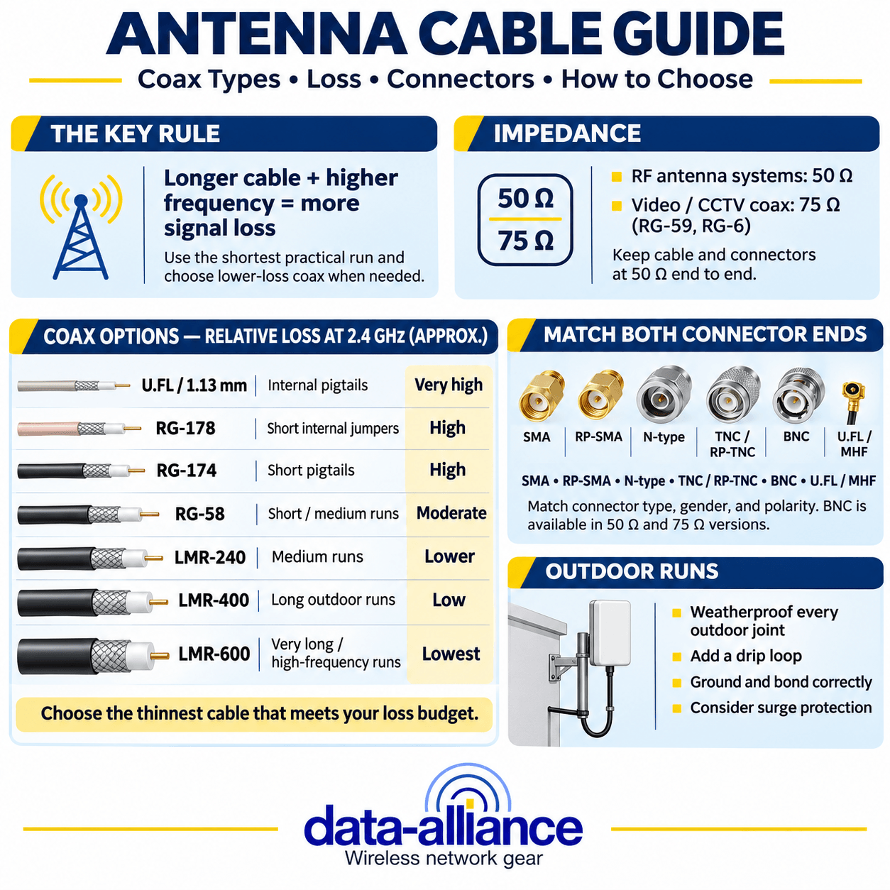
| Common coax | 1.13 mm, 1.37 mm, RG-178 | Thinner = more flexible but higher loss/ft |
Two of these drive most sourcing mistakes: mating cycles (people treat U.FL like a reusable connector and crack the header), and coax choice, where thin cable keeps the assembly flexible but adds real loss over even short runs.
U.FL vs MHF / IPEX generations
The confusion that costs integrators the most time is treating every tiny snap-on connector as "U.FL." The micro-coaxial family has shrunk over successive generations, and the generations are not cross-compatible. Match the series on both ends.
| Family | Common alias | Relative size | Notes |
|---|---|---|---|
| U.FL | IPEX (Gen 1), IPX, AMC | Largest of the micro group | The baseline interface this guide covers |
| MHF1 | IPEX MHF, W.FL | Comparable to U.FL | Often U.FL-interchangeable, but confirm |
| MHF3 | IPEX 3 | Smaller | Not interchangeable with U.FL/MHF1 |
| MHF4 | IPEX 4, IPEX MHF4 | Smallest, common on M.2 | Dominant on modern WiFi 6/6E M.2 modules |
If your module is a recent M.2 WiFi/Bluetooth or 4G/5G card, the port is very likely MHF4, not U.FL — the plugs look similar but do not mate. See our MHF1 / MHF3 / MHF4 connectors and cables to match the exact generation your radio uses.
How to choose a U.FL pigtail or cable
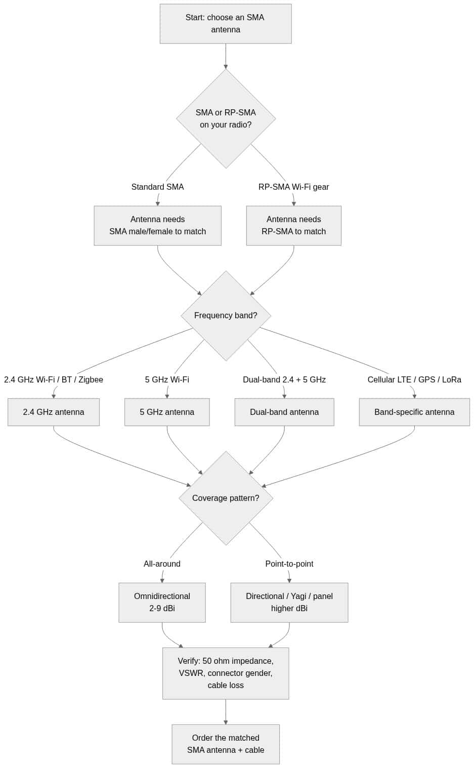
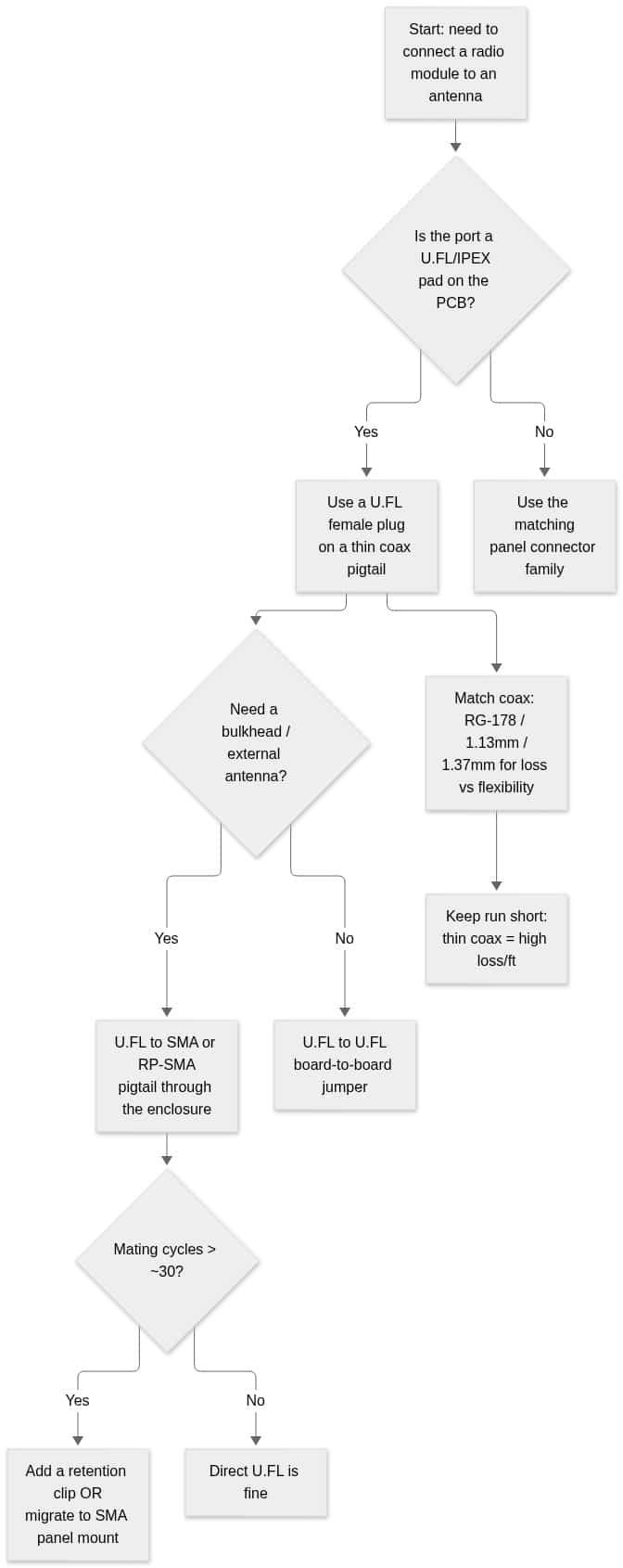
In practice you rarely buy a bare U.FL connector — you buy a pigtail: a short pre-terminated coax with a U.FL female plug on the board end and a bulkhead connector (SMA or RP-SMA) on the enclosure end, so an external antenna can attach. Use this decision flow to spec the assembly:
1. Confirm the board-side interface
Identify whether the port is true U.FL/IPEX Gen 1 or an MHF variant before anything else. A U.FL plug will not seat on an MHF4 header and forcing it damages both.
2. Pick the enclosure-side connector
SMA and RP-SMA are the usual bulkhead ends. RP-SMA is standard on consumer WiFi gear; standard SMA is common on LTE/GPS and most non-WiFi radios. Get the gender and polarity right so the external antenna mates. Our guide to SMA connector specifications and characteristics is a useful cross-check when you are matching the panel end.
3. Match the coax to loss vs. flexibility
U.FL pigtails use thin coax — commonly 1.13 mm, 1.37 mm, or RG-178. Thinner cable routes easily inside tight enclosures but has higher attenuation per foot, so keep runs as short as the layout allows. For a deeper look at how micro-coax types compare on shielding and loss, see our comparison of U.FL cable coax types (1.13 mm, 1.32 mm, 1.37 mm, RG-174, RG-178). If you need a longer run, transition to a lower-loss cable such as LMR after the bulkhead rather than extending thin coax; our comparison of LMR-100, LMR-200 and LMR-400 coax shows the loss trade-offs by cable size.
4. Account for VSWR across the chain
Every connector transition and length of coax affects the match seen by the radio. Keep the system at 50 ohms end to end and watch the total loss budget; our explainer on VSWR and impedance matching in antennas covers why a clean match matters more than raw antenna gain in many compact installs.
Handling and reliability in the field
Because U.FL is a snap fit with a low mating-cycle rating, treat it as a build-time connector. Remove a plug by lifting straight up with a proper U.FL removal tool or fingernail at the connector body — never pull on the coax, which rips the center conductor or lifts the board pad. For installations that will be opened repeatedly, or that face vibration, use a locking clamp / retention clip for U.FL connectors to keep the plug seated, or design the external interface around a robust SMA bulkhead so the U.FL joint is only made once.
Where to buy U.FL connectors and pigtails
Data Alliance manufactures custom U.FL and MHF pigtails to your exact length, coax type and bulkhead connector. Browse our antenna cables and adapters, or if your module uses the smaller interface, our MHF4-to-U.FL cables in multiple lengths. Need a non-standard assembly? Request a custom quote, or contact our technical support team to confirm the right connector family for your radio before you order.
Frequently asked questions about U.FL connectors
Is U.FL the same as IPEX?
For the first-generation interface, effectively yes. "U.FL" is Hirose's trademark; "IPEX," "IPX," and "AMC" are compatible equivalents from other makers. The caveat is the later generations — IPEX MHF3 and MHF4 are smaller and do not intermate with U.FL, so check the series, not just the name.
Is a U.FL connector the same as MHF4?
No. MHF4 (IPEX 4) is a smaller, newer interface common on M.2 WiFi 6/6E and cellular modules. A U.FL plug will not mate with an MHF4 header. If your module is a recent M.2 card, assume MHF4 until you confirm otherwise.
How many times can you plug and unplug a U.FL connector?
Datasheets commonly rate U.FL for around 30 mating cycles. It is designed as a build-time connector, not one for repeated field connection. If you will mate it often, add a retention clip or route the signal to an SMA bulkhead for the external connection.
What coax is used on U.FL pigtails?
Thin micro-coax — typically 1.13 mm, 1.37 mm, or RG-178 — which stays flexible inside tight enclosures. The trade-off is higher loss per foot than larger cable, so keep U.FL runs short and transition to lower-loss coax after the bulkhead for longer runs.
How do I remove a U.FL connector without damaging the board?
Lift straight up at the connector body using a U.FL removal tool (or carefully with a fingernail) — never pull the coax. Pulling the cable can tear the center conductor or lift the board-side pad, which usually ruins the port.
What frequency range does U.FL support?
Typical U.FL series are specified from DC up to roughly 6 GHz depending on the exact part, which covers 2.4 GHz and 5 GHz WiFi, Bluetooth, LTE, GPS and sub-GHz IoT. Confirm the rated range on the specific connector's datasheet for your band.