


Antennas, Antenna Cables, Wireless Products: Technical Articles
U.FL Connector Guide: What It Is, Specs, and How to Choose the Right Cable
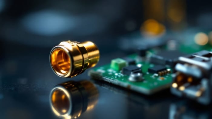
A U.FL connector is a miniature 50-ohm coaxial RF connector used to attach an antenna, pigtail, or board-to-board jumper to a compact wireless device. Originally developed by Hirose as the U.FL series and widely second-sourced as IPEX MHF1, it is the connector you find on mini-PCIe WiFi cards, LTE and GPS modules, and dense IoT boards where a full-size SMA jack simply will not fit. If you are choosing a U.FL connector or a U.FL cable, the decisions that matter are the connector series, the coax diameter, the mating-cycle budget, and what the other end of the cable needs to terminate into.
What is a U.FL connector?
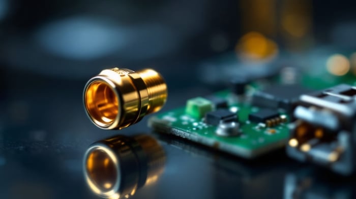
The U.FL connector is a snap-on (push-fit) micro-coaxial connector with a 50-ohm characteristic impedance. The plug (on the cable) presses vertically onto a surface-mounted jack (receptacle) on the PCB — there are no threads and no keying. Because it relies on a small interference fit rather than a threaded coupling, it is compact and fast to seat, but it also has a limited number of mate/unmate cycles and can be pulled off by cable strain, which is a common failure mode in the field.
"U.FL" is Hirose's brand name; "IPEX MHF1" is the equivalent from I-PEX; other vendors sell compatible parts under names like AMC or MHF. In practice these are treated as intermateable within the same series, but you should always confirm mechanical compatibility on the manufacturer datasheet before mixing brands, especially for the mating force and retention.
U.FL connector specifications to verify
The table below lists the commonly cited U.FL (MHF1) parameters. Treat these as typical values for the series — the exact numbers vary by manufacturer and part number, so verify the figures for your specific U.FL connector against its datasheet before you design them into a product.
| Parameter | Typical U.FL / MHF1 value | Why it matters |
|---|---|---|
| Impedance | 50 ohm | Must match the radio and coax for low VSWR |
| Frequency range | DC to ~6 GHz | Covers 2.4/5 GHz WiFi, LTE, GPS, sub-GHz IoT |
| Mated height | ~2.5 mm (low-profile) | Fits under covers and stacked boards |
| Mating cycles | ~30 (limited) | Snap-fit wears — not for frequent reconnection |
| Compatible coax | 1.13 mm, 1.37 mm, RG-178, RG-174 | Sets flexibility vs. cable loss |
| Retention | Friction fit only | Prone to pop-off under cable strain |
The two figures that catch people out are the mating-cycle limit and the retention. U.FL is designed to be mated a handful of times during assembly, not repeatedly in service. If your application requires frequent disconnects, plan for a strain-relieved cable and route the U.FL end so it is never the connector the user handles.
U.FL vs MHF4 (and other micro-coax connectors)
U.FL is the original of a family that has shrunk over successive generations. The most common comparison is U.FL vs MHF4, because they look similar but are not intermateable. MHF4 (IPEX MHF4) is smaller and uses thinner 0.81 mm coax, so it is used on the most space-constrained modules — M.2 WiFi/BT cards being the classic example.
| Series | Also known as | Typical coax | Relative size | Typical use |
|---|---|---|---|---|
| U.FL | IPEX MHF1, AMC | 1.13 / 1.37 mm | Largest of the micro group | mini-PCIe cards, IoT, GPS, LTE modules |
| MHF3 / W.FL | IPEX MHF3 | 0.81 mm | Smaller than U.FL | Compact modules, some cellular |
| MHF4 | IPEX MHF4 / MHF4L | 0.81 mm | Smallest common | M.2 WiFi/BT, ultra-dense boards |
The practical rule: identify the jack on your board first, then match the plug series. A U.FL plug will not seat on an MHF4 jack, and forcing it damages both. For a broader walk-through of every RF interface, see our antenna connector types guide, and if the board uses MHF4 rather than U.FL, our 0.81 mm coaxial cable article covers the thinner coax those series use.
How to choose the right U.FL cable
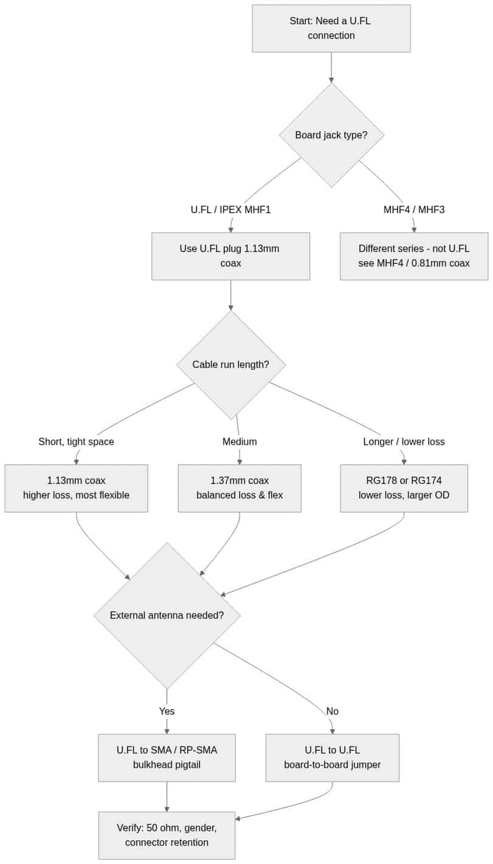
Once the connector series is settled, the U.FL cable itself is defined by three choices: the coax type, the length, and what the far end terminates into. The flowchart below shows the decision path.
1. Pick the coax diameter
Thinner coax is more flexible and fits tighter enclosures but has higher loss per unit length; thicker coax lowers loss at the cost of flexibility and a larger bend radius. For U.FL assemblies the usual options are 1.13 mm and 1.37 mm micro-coax, with RG-178 and RG-174 available where a longer run needs lower loss. Our U.FL cables coax types comparison gives the size-versus-loss trade-offs, and the bend radius guide for U.FL coax is worth reading before you route a cable inside a tight housing.
2. Match the far-end connector
If the U.FL end connects a board to an external antenna, the far end is usually a bulkhead SMA or RP-SMA so the antenna mounts through the enclosure wall. A U.FL to SMA (or RP-SMA) pigtail is the standard building block here. Get the gender and polarity right: WiFi gear frequently uses RP-SMA, while cellular, GPS and most other RF use standard SMA. Our SMA connector specifications guide explains SMA versus RP-SMA and male versus female so you order the correct pairing.
3. Confirm impedance and retention
Keep the whole path at 50 ohms and plan for strain relief. Because U.FL retention is friction-only, a cable clip, a dab of adhesive, or an MHF4L-style locking series (on boards that support it) prevents the pop-off failures that show up as intermittent connectivity.
Where U.FL connectors are used
- WiFi / Bluetooth modules — mini-PCIe and embedded radios with an internal U.FL jack for an external antenna.
- LTE / cellular modems — main and diversity/MIMO antenna ports on M2M and router boards.
- GPS / GNSS receivers — feeding an active patch antenna into a compact receiver.
- IoT and gateway boards — sub-GHz and 2.4 GHz radios where board space is at a premium.
Ready to build the link? Browse Data Alliance's U.FL cables and pigtails for U.FL-to-SMA/RP-SMA assemblies, or see the full range of antenna cables and adapters. Data Alliance custom-manufactures U.FL cable assemblies to length and connector spec — request a custom quote if you need a non-standard configuration.
Frequently asked questions
Is U.FL the same as IPEX?
Practically, yes for the first generation. "U.FL" is Hirose's series name and "IPEX MHF1" is the intermateable equivalent from I-PEX; many vendors also label compatible parts as AMC or MHF. They are treated as the same connector family, but confirm mechanical and electrical compatibility on the datasheet before mixing brands.
What is the difference between U.FL and MHF4?
MHF4 (IPEX MHF4) is a smaller, later-generation micro-coax connector that uses thinner 0.81 mm coax and is common on M.2 WiFi/Bluetooth cards. U.FL (MHF1) is larger and uses 1.13 mm or 1.37 mm coax. They are not intermateable — a U.FL plug will not seat on an MHF4 jack — so identify the jack on your board before ordering.
How many times can you plug and unplug a U.FL connector?
U.FL is a snap-fit connector with a limited mating-cycle rating — commonly cited around 30 cycles, though the exact figure varies by manufacturer. It is intended for occasional mating during assembly, not repeated reconnection. Check the datasheet for your specific part and use strain relief to avoid accidental disconnects.
Can I connect a U.FL board to an external SMA antenna?
Yes — use a U.FL to SMA (or RP-SMA) pigtail. The U.FL plug snaps onto the board jack and the bulkhead SMA/RP-SMA mounts through the enclosure so an external antenna can attach. Match the gender and polarity: WiFi hardware often uses RP-SMA, while cellular and GPS typically use standard SMA.
What coax is used with U.FL connectors?
The most common options are 1.13 mm and 1.37 mm micro-coax, with RG-178 and RG-174 used where a longer run needs lower loss. Thinner coax is more flexible for tight enclosures but has higher loss per length; thicker coax lowers loss but needs a larger bend radius.