


Antennas, Antenna Cables, Wireless Products: Technical Articles
Double Shielding of Antenna Cables for Low Signal Loss
Table of Contents
- Interference and Cable Shielding
- How Shielding Works
- RG standard of Coaxial Cable
- RG58 Compared to LMR-200 & LMR-100 Coax: Shielding & Signal Loss
- RG-174 compared to LMR-100 Coax: Shielding and Signal Loss
- Why Double Shielding Matters in Modern IoT, LTE & 5G Installations
- Double Shielding in MIMO Systems
- Shielding Effectiveness (SE) Explained
- Shielding vs VSWR
- Grounding Best Practices for Antenna Cables
- Selecting the Right Coaxial Cable for Your Application
- Conclusion: Why Double Shielding Matters
- FAQs
Interference and Cable Shielding
Shielding protects against both leakage and absorption of stray radiation of electrical noise by cables.
- Electrical "signal noise" interferes with the operation of antennas and antenna cables.
- Cables carrying high-frequency charge naturally pose the risk of EMI transfer - both from radiating and receiving EMI (electromagnetic interference).
While insulation protects antenna cables from physical damage due to the forces of impact or compression, shielding deflects the environmental challenges of EMI.
High levels of EMI radiation should be expected where appliances with high current electrical equipment are present, like transformers (for example).
How Shielding Works
Shielding within the composition of a coaxial cable functions in two ways:
- It reflects any EMI generated by the inner conductor (which carries the electrical charge/signal) and
- It catches external noise while grounding it, thus sparing the inner conductor from interference & preserving the inner signal transmission.
No shield protection within cabling is impenetrable, but the aim is to sufficiently dampen (attenuate) the noise such that it doesn't interfere with the signal carried.
Shielding methods vary. Increased shielding is required in especially noisy environments challenged by many sources of high-load interference, and the converse is expected in less noisy locations.
Is there any downside to cable shielding?
Shielding reduces flexibility and increases the diameter of cables, which can be an issue in tight spaces, such as device cases and enclosures.
Cable shielding comes at a budgetary cost, so a carefully calculated trade-off should be considered, but without compromising mission-critical signal transmission quality.
Types of Shielding in Coaxial Antenna Cables
1. Aluminum foil shield
A layer of aluminum, reinforced for strength, is usually girded by polyester. This type of shield covers the conductor 100%—i.e., the aluminum shield has no breaches in its integrity. This makes for a good shield.
2. Copper braided shield
These comprise braided strands of copper metal, which, by nature of the formation, do not offer 100% coverage (due to gaps between braided bunches). However, tighter braids can be used for increased coverage. Braided shields typically offer between 70% and 100% coverage.
Which shield is more effective?
Contrary to what you may think (according to the concept of coverage), the copper braided shield offers the greatest noise attenuation.
Why? The density of the braided copper material simply blocks out more noise. However, more material is more expensive and also heavier.
Is there ever cause to use both shields?
Yes, aluminum and copper braided shields are used in high EMI environments.
Where wires are twinned together in a cable, aluminum is used as an inner cover to prevent 'cross-talk' between conductors, and then the outer cabling is shielded by dense copper braiding.
Grounding the noise
The key to good shielding is ensuring the noise is grounded once it is picked up by the shield. So, good practice would be to have every cable grounded to carry away the noise, maintaining the effectiveness of your shield.
RG standard of Coaxial Cable
RG is a robust coaxial technology standard - one of the original standards for coaxial cable technology, created for the US military in the 1960's. RG is not a specific manufacturer's standard: All coax manufacturers can use RG and a standard by using the letters RG ("Radio Guide") followed by a number corresponding to a certain standard with a particular set of specifications. Sometimes, the letter "/U" follows the number for the "Universal" standard (i.e., the cable construction is intended for universal applications).
There is no standardization among manufacturers to ensure that every aspect of the cable is constant, so it helps to know the specifications of the cable you need.
RG technology is used in military and commercial applications in various environments.
Generally, 75 Ohm cables are used in audio/video applications, and 50 Ohm cables are used in data applications. The 50 Ohm RG cables typically lose too much signal through attenuation to be appropriate for wireless applications unless the cable is short. Low-loss coax is the only viable solution for antenna cables of longer lengths.
RG58 Compared to LMR-200 & LMR-100 Coax: Shielding & Signal Loss
RG58 Coaxial Cable Specifications
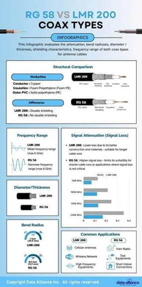
RG58, LMR-100, and LMR-200 all have the following characteristics in common:
- 50 Ohm impedance
- A weather-resilient polyethylene (PE) dielectric
- PVC outer jacket
Structural comparison of RG58 and LMR-100 (aside from what is mentioned above):
- LMR-100 is a 50 Ohm coaxial cable that shares structural and material similarities with RG58 but has an overall lower diameter of 2.79mm (0.110 inches).
- RG58 and LMR-100 have the following key differences:
- LMR-100 carries a solid bare copper-covered steel (BCCS) central conductor of 0.46mm.
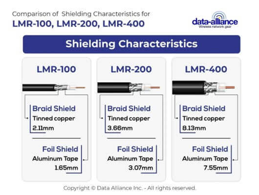
- LMR-100 is a double-shielded coaxial cable. The inner shield is made from aluminum tape, and the outer shield is braided, tinned copper.
Structural comparison of RG58 and LMR-200 (aside from what is mentioned in the first paragraph above):
- LMR-200 is a larger diameter (6.1mm 0.24inches) low-loss coaxial cable. Double shielding improves EMI rejection and signal integrity in noisy RF environments. Lower attenuation in LMR-type cables is primarily due to larger conductors and improved dielectric design.
- LMR-200 possesses a more prominent conductor of 1.42mm diameter made from bare copper (BC)
ATTENUATION | Signal Loss: dB/ft. | Signal Loss: dB/ft. |
Frequency (MHZ) | RG58 | LMR-200 |
100 | 0.048 | 0.038 |
200 | 0.073 | 0.048 |
400 | 0.114 | 0.068 |
500 | 0.125 | 0.070 |
900 | 0.195 | 0.228 |
1000 | 0.213 | 0.119 |
1500 | 0.245 | 0.129 |
2400 | 0.354 | 0.169 |
About RG58
Electrical characteristics of RG58: The typical impedance is within a 2 Ohm range of 50 Ohm. It operates at frequencies up to 5GHz. The conductor resistance is 38.4 Ohm. The dielectric resistance is 500 Ohm.
Structure and material composition of RG58 cable
Like all other coaxial cables, RG58 comprises an inner conducting wire surrounded by an insulating layer and outer conducting shielding. It is typically manufactured to the U.S. specifications MIL-C-17F and MIL-C-17G 9.
- The conductor has a diameter of 0.91mm (0.036 inches) and is made from stranded (7 or 19 strand tinned copper wire, which has added resistance to oxidation and is readily soldered. Solid conductor variants are also available.
- The dielectric diameter is 2.95mm (0.116 inches), made from solid polyethylene (PE). Polythene is heat stable up to a maximum operating temperature of 80 degrees Celsius (176 degrees Fahrenheit) and provides flexibility, fire resistance, resilience against abrasions, and weatherproofing.
- RG58 is shielded with flexible and heat-stable tinned copper wire braid, with coverage between 70% and 95%, depending on the manufacturer.
- The outer jacket of the RG58 cable is made from UV-resistant PVC, which is heat-stable but has limited resistance to acids, alkalis, and inorganic solvents.
- The overall diameter of this cable is 5mm (0.2 inches).
RG58 is a coaxial cable type for antenna cables made to strict U.S. government specifications. The ‘RG’ prefix stands for ‘Radio Frequency Government,’ and the number refers to the gauge of the cable.
RG58 applications
This coax cable performs well for various radio frequency communication applications in a low-power setting. Key applications include:
- Testing and measurement
- Ham and emergency services radio
- Marine VHF
- WLAN antennas
When to Use RG58 vs LMR-Type Low-Loss Coax
Use RG58 when:
- Cable runs are under 10–15 feet
- Low-power RF systems
- Temporary installations
- Cost-sensitive projects
Use LMR-100 when:
- Small diameter is required
- Moderate cable lengths
- Indoor IoT installations
- Better shielding than RG174 is required
Use LMR-200 when:
- Cable runs exceed 15–25 feet
- LTE or 5G routers
- Outdoor antennas
- Lower attenuation is critical
Use LMR-400 when:
- Long cable runs (50+ feet)
- Base station or gateway installations
- Industrial or municipal deployments
- Maximum signal retention is required
RG-174 compared to LMR-100 Coax: Shielding and Signal Loss
LMR-100 and RG174 Coaxial Cable Comparison
- RG174 and LMR-100 are compatible with Wi-Fi, Cellular, and most IoT wireless applications.
- LMR-100 is double-shielded and suitable for outdoor as well as indoor use.
- RG174 has a single shield and is unsuitable for long-term outdoor use.
ATTENUATION | Signal Loss: dB/ft. | Signal Loss: dB/ft. |
Frequency (Mhz) | RG174 | LMR-100 |
100 | 0.088 | 0.038 |
200 | 0.140 | 0.100 |
400 | 0.220 | 0.146 |
500 | 0.159 | |
900 | 0.300 | 0.228 |
1000 | 0.320 | |
1500 | 0.301 | |
2400 | 0.750 | 0.390 |
Understanding Attenuation in Real Installations
Example:
At 2400 MHz (WiFi band):
- 50 ft of RG174 ≈ 37.5 dB loss (0.75 dB/ft × 50 ft)
- 50 ft of LMR-100 ≈ 19.5 dB loss
- 50 ft of LMR-200 ≈ 8.45 dB loss
- 50 ft of LMR-400 ≈ ~3.4 dB loss
A 3 dB loss represents 50% signal reduction.
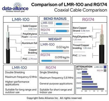
RG174 is a small, flexible coax for antenna cables with an American Wire Gauge of 26. Its diameter is 2.79mm (0.11 inches). Its relatively small diameter, flexibility, high speed, and efficient data transfer make it an ideal choice for a wide range of contemporary and consumer applications, including:
- Security and access control
- Automation and IoT networking
- GPS
- Wireless networking such as LAN/WAN:
- For Wi-Fi: Most typically RP-SMA, cables
- For LTE: SMA cables or N-Type cables
RG174 Physical Characteristics:
RG174's structure is typical of coaxial cables and is comprised of the following layers and materials:
- Central conductor: 7 strands of stranded copper-clad steel (CCS) with a diameter of 0.483mm (0.019 inches).
- Dielectric: Low-density polyethylene (LDPE), which contributes water resistance and flexibility to the cable. The dielectric diameter is 1.55mm (0.06 inches)
- Outer shielding: A single layer of tinned copper with coverage between 88% and 90%, depending on the manufacturer.
- Jacket: Polyvinyl Chloride (PVC), a flexible weather-resistant coating with good flame resistance. Due to its material composition (plastics), the operating temperature of this cable is between -40 and 80 degrees Celsius (-40 degrees to 176 degrees Fahrenheit).
Electrical profile of RG174
The impedance of RG174 is typically 50 Ohm. The conductor resistance is a maximum of 142.4 Ohm, and the dielectric resistance is at least 1000 Ohm. This cable transmits a maximum frequency of 6GHz.
Comparison of RG174 and LMR-100 coax cable
Key Features:
- RG174:
- Diameter: Typically, around 2.79mm.
- Impedance: Standard 50 ohms.
- Velocity of Propagation: Approximately 66%.
- Attenuation: Higher than LMR-100, especially over longer distances.
- LMR-100:
- Diameter: Roughly 2.79mm, similar to RG174.
- Impedance: Maintains the 50 ohms industry standard.
- Velocity of Propagation: Slightly higher than RG174 at around 70%.
- Attenuation: Provides better performance with lower loss over extended distances.
Materials Composition:
- RG174: RG174 coaxial cables often consist of a silver-plated copper center conductor surrounded by a dielectric insulator, typically solid polyethylene. This assembly is then covered by a shield, usually made from tinned copper, followed by an external PVC jacket.
- LMR-100: This cable features a copper center conductor, often silver-plated, and a gas-injected foam polyethylene dielectric core. LMR-100 is recognized for its dual shielding, with the inner layer being aluminum and the outer layer made from tinned copper braid, all enveloped in a durable polyethylene jacket.
Types:
RG174 and LMR-100 come in various versions specially designed for specific environments. You can find these cables in their regular form as ultra-flexible versions, or even with UV resistance for outdoor installations.
Associated Wireless Technologies:
- RG174: Due to its higher Attenuation, RG174 is commonly employed in low-power, short-distance applications, such as Wi-Fi antennas, GPS systems, and mobile communications.
- LMR-100: LMR-100, with its superior Attenuation performance, finds applications in a broader range of wireless technologies, including 2G/ 3G/4G cellular, WLAN, RFID, and more.
Applications & Suitability for Specific IoT Applications:
IoT revolves around connectivity, requiring reliable transmission lines.
- RG174: Suitable for indoor IoT applications where the cable run is short. Ideal for connecting Wi-Fi-based IoT devices, short-range sensors, and indoor antennas.
- LMR-100: Given its low loss characteristics, LMR-100 is more appropriate for indoor and outdoor IoT deployments, particularly where longer cable runs are involved. If you're looking at IoT applications such as outdoor weather stations, smart agriculture, or city-wide sensor deployments, LMR-100 stands out as the preferred choice.
Why Double Shielding Matters in Modern IoT, LTE & 5G Installations
In today’s RF environments, interference is significantly higher than in legacy analog systems. Cellular towers, Wi-Fi routers, Bluetooth devices, industrial machinery, switching power supplies, and LED drivers all contribute to background RF noise.
For applications such as:
- LTE routers
- 5G gateways
- Industrial IoT sensors
- Smart agriculture systems
- Remote monitoring systems
- Public safety communications
- MIMO antenna arrays
Double-shielded coaxial cables (foil + braid) provide:
- Higher shielding effectiveness (typically >90 dB)
- Reduced ingress and egress interference
- Improved signal stability at higher frequencies (700 MHz – 6 GHz)
- Better performance in multi-antenna (MIMO) deployments
Data Alliance recommends double-shielded low-loss coax for mission-critical wireless connectivity, especially in outdoor or industrial environments.
Double Shielding in MIMO Systems
Modern LTE and 5G routers use MIMO (Multiple Input Multiple Output) technology requiring 2, 4, or even 8 antenna cables.
In MIMO installations:
- Cables are routed in close proximity.
- Poor shielding can cause inter-cable coupling.
- Cross-talk degrades throughput performance.
Double-shielded coax minimizes inter-channel interference and ensures optimal MIMO performance.
For 4x4 or 8x8 MIMO deployments, shield quality becomes increasingly important.
Shielding Effectiveness (SE) Explained
Shielding effectiveness is measured in decibels (dB) and indicates how well a cable blocks electromagnetic interference.
- 60 dB = 99.9% attenuation of interference
- 90 dB = 99.9999999% attenuation
- 100+ dB = High-performance RF-grade shielding
Foil shields provide:
- 100% coverage
- Excellent high-frequency shielding
Braided shields provide:
- Mechanical strength
- Low-frequency EMI protection
- Better grounding path
Foil + braid combinations provide broadband protection across both low and high frequencies.
This is why most professional-grade IoT antenna cables use dual shielding.
Shielding vs VSWR
It is important to note:
- Shielding affects noise immunity.
- VSWR (Voltage Standing Wave Ratio) affects signal reflection.
- Attenuation affects signal strength.
All three must be optimized in professional RF installations.
Poor shielding can raise the system noise floor, while poor VSWR reduces power transfer efficiency.
Grounding Best Practices for Antenna Cables
Proper grounding is essential for effective shielding performance.
Recommendations:
- Ensure connectors are securely terminated with proper crimp or compression fittings.
- Use grounded bulkhead connectors when passing through metal enclosures.
- Ground outdoor antenna masts according to local electrical codes.
- Install lightning arrestors for rooftop or mast-mounted antennas.
- Avoid ground loops by maintaining a single-point grounding strategy.
Poor grounding can reduce shielding effectiveness and introduce additional noise into the RF system.
Data Alliance technical support can assist in selecting grounding-compatible connectors and lightning protection accessories.
Selecting the Right Coaxial Cable for Your Application
Choosing the correct coaxial cable depends on:
- Frequency range
- Cable length
- Environmental exposure
- Connector type (SMA, RP-SMA, N-Type, TNC, etc.)
- Flexibility requirements
- Installation routing constraints
- EMI exposure level
Data Alliance offers:
- Custom-length LMR-type assemblies
- SMA, RP-SMA, N-Type, TNC connectors
- Outdoor-rated polyethylene jackets
- UV-resistant options
- Low-PIM cable options
- Technical support for antenna and cable matching
For assistance selecting the correct cable for your IoT, LTE, or 5G installation, contact our RF technical support team.
Conclusion: Why Double Shielding Matters
As wireless systems evolve toward higher frequencies and higher data throughput, shielding performance becomes increasingly important.
Double-shielded coaxial cables provide:
- Superior EMI rejection
- Greater signal stability
- Improved MIMO performance
- Better long-term reliability
- Increased protection in industrial and outdoor environments
For short indoor runs, RG cables may suffice. For mission-critical IoT, LTE, and 5G systems, low-loss double-shielded coaxial cable is strongly recommended.
Data Alliance provides professional-grade antenna cable assemblies engineered for performance, durability, and signal integrity.
FAQs
What does “double-shielded” coax mean?
Double-shielded coax uses two shielding layers—typically an aluminum foil (100% coverage) plus an outer copper braid. Together, they improve EMI rejection, reduce noise ingress/egress, and help maintain signal integrity in real-world RF environments (Wi-Fi, LTE, 5G, IoT).
Does double shielding reduce signal loss (attenuation)?
Not directly. Attenuation is mostly driven by conductor size, dielectric type, frequency, and overall cable design.
Double shielding primarily improves noise immunity and signal stability, especially in high-EMI areas. Low-loss LMR-type cables typically have lower attenuation because of larger conductors and improved dielectric design, not because of shielding alone.
What’s the difference between foil shielding and braided shielding?
- Foil (aluminum tape) shield:
- 100% coverage
- Excellent high-frequency shielding
- Helps block RF leakage through “gaps”
- Braided copper shield:
- Usually 70–100% coverage (depends on braid density)
- Strong mechanical protection and good grounding path
- Performs well for lower-frequency EMI and durability
Most professional antenna cables use foil + braid for broad-spectrum protection.
Which shield is more effective—foil or braid?
In practice, braid often provides stronger overall attenuation of certain types of noise because of its metal density and grounding performance, while foil provides complete coverage and is strong at higher frequencies. For many LTE/5G/IoT installations, the best answer is: use both (foil + braid).
When should I choose RG58 vs LMR-100 vs LMR-200 vs LMR-400?
A quick rule of thumb:
- RG58: short runs (about 10–15 ft), lower-power, temporary, cost-sensitive
- LMR-100: small diameter, moderate lengths, indoor IoT, better shielding than RG174
- LMR-200: longer runs (about 15–25+ ft), LTE/5G routers, outdoor antennas, lower attenuation than smaller coax
- LMR-400: long runs (50+ ft), gateways/base stations, industrial/municipal deployments, maximum signal retention
Why is RG174 usually not recommended for long outdoor antenna runs?
RG174 is small and flexible but has higher attenuation, and many versions use PVC jackets that aren’t ideal for long-term UV/weather exposure. For outdoor and longer runs, a double-shielded low-loss coax like LMR-100/LMR-200/LMR-400 is typically the better choice.
Why does grounding matter for shield performance?
Shielding works best when interference collected by the shield has a clear path to ground. Poor terminations, loose connectors, and bad grounding practices can reduce shielding effectiveness and even introduce noise. Best practices include:
- Proper connector termination (crimp/compression as required)
- Grounded bulkheads through metal enclosures
- Outdoor mast grounding per local code
- Lightning arrestors for rooftop/mast antennas
- Avoiding ground loops with single-point grounding
How does double shielding help in LTE/5G MIMO installations?
MIMO systems use multiple antenna cables (2x2, 4x4, 8x8). When cables run close together, poor shielding can increase inter-cable coupling and cross-talk, which can reduce throughput. Double shielding helps:
- Reduce interference between adjacent RF lines
- Keep the noise floor lower
- Improve stability at 700 MHz–6 GHz ranges common in modern cellular/IoT gear