


Antennas, Antenna Cables, Wireless Products: Technical Articles
BNC cables for Video: 3G-SDI and HD-SDI SMPTE 424M Standard
Table of Contents
BNC Cables for Video:
In professional video systems, the cable assembly is not an accessory—it’s a critical part of the signal path. HD-SDI and 3G-SDI links depend on consistent 75-ohm impedance, controlled attenuation, and properly matched BNC connectors to preserve signal integrity, minimize reflections, and reduce jitter over distance. This guide explains the fundamentals of SMPTE 424M–compliant BNC cable assemblies and how to select the right coax (RG59, RG179, and related options) for your installation. Data Alliance supports broadcast, surveillance, industrial, and OEM applications with standard and custom BNC cable assemblies, engineering guidance, and performance-focused recommendations based on distance, environment, and bandwidth requirements.
Data Alliance’s BNC cables made with RG59 and RG179 are compliant with the SMPTE 424M standard for 3G-SDI and HD-SDI video systems.
SMPTE-compliant BNC Digital Video Cables: 75-Ohm: RG59 and RG179
BNC 75 Ohm cables are a version of BNC coaxial cable assemblies that is widely used for audiovisual applications. It consists of a length of 75 Ohm impedance coaxial cable that is terminated at both ends by 75 Ohm Bayonet Neill Concelman (BNC) connectors. The impedance of both the cable and connectors is distinct and routinely incompatible with 50 Ohm versions.
The quality of the cable is critical to the overall performance of an SMPTE-compliant video system. A dysfunctional or failed cable will affect all the channels and potentially prevent the audio equipment from functioning.
The Society of Motion Picture and Television Engineers (SMPTE) is an audiovisual and media group that comprises media professionals, engineers, and technologists who have produced over 600 industry standards for the digital transfer of video over coaxial and fiber optic cable . This type of video signal transfer over multiple wired links is known as Serial Digital Interface (SDI).
The standards cover aspects of digital video data transfer that include physical layer characteristics , image formats, encoding, payload, and timings.
These standards have contributed to the widespread adoption of uncompressed video that is low latency, cost-effective and advantageous in real-time surveillance and mission-critical applications. Though initially developed in the broadcast media industry SDI is frequently used in defense or law enforcement sectors for video-based mission systems.
The third generation of SDI is known as 3G-SDI and is a revision of the SMPTE 424M standard which specifies a video resolution of 1080 pixel video with 60 frames per second and data transfer speeds of up to 3 Gigabit per second.
SMPTE Characteristics
Color images are serially encoded and transferred using RGB tristimulus values that are linearized and then corrected to approximate the perceptual responses of human vision.
Also luma, (derived from RGB) and chroma (color difference) component values are used in SDI video systems.
SDI uses system nomenclature that delivers the active video format of an image with a resolution of 1920 by 1080 pixels.
3G-SDI Physical Layer
3G-SDI uses a coaxial interface for the distribution of video signals in broadcast environments. Coax-based 3G-SDI networking uses Emitter-Coupled-Logic (ECL) a high-speed technology with a propagation speed of under 2 nanoseconds. The system impedance is 75 Ohms and the input/output voltages may be up to 0.8 volts. Transmission along the lines is unidirectional. Coaxial cables used for 3G-SDI are terminated with the BNC connectors described above.
Best cable for 3G-SDI SMPTE 424-M
The SMPTE 424M standard does not detail the exact type of coax to be used in BNC cable assemblies, other than specifying:
- An impedance of 75 Ohms.
- The attenuation in decibels should be proportional to the square root of the frequency transmitted, especially for longer cable lengths.
On this basis, SDI uses RG 59U or RG-6 cable. RG-179 may also be used for shorter runs. The SMPTE standard states that the use of 50 Ohm BNC connectors with 75 Ohm cable is not compliant, though this practice has been used for lower bandwidth composite video. The cable should be stored and handled properly to ensure that any signal degradation is minimized.
The video is encoded and the serialized data is scrambled before being transmitted as a bitstream down the coax cable. The SDI data payload includes the syncing, Timing Reference Signals (TRS) for the video and active video data is transferred at speeds between 143 Mbps and 3 Gbps. Ancillary data can also be simultaneously transferred in areas of the data stream not occupied by the video.
Other standardized physical layer SDI components that work with BNC connector cables include:
- SDI Transmitters or Serializers are devices that are capable of integrating a range of signal components and audio processing for fast and effective video streaming, which saves cost and power.
- SDI Cable Drivers are designed to drive SDI signals along a longer length of coaxial cable. They work to overcome the signal attenuation that takes place with long lengths of coax cable.
- Cable Equalizers are SDI components that compensate for coax cable losses along their length. They can be multi-rate and multi-channel and are used particularly with High Definition (HD) and Ultra High Definition (UHD) video equipment.
- Reclockers are used to retrieve a clean time sequence or clock from an SDI video that has been affected by jitter. The video can then be re-synchronized.
Coax-based 3G-SDI systems require drivers and equalizers to perform optimally.
The physical media for 3G-SDI broadcast video requires components like equalizers to perform optimally. This is because the passage of audiovisual digital signals through cable and other components will degrade ( phase distortion and attenuation) the signal, with the cable functioning as a low-pass filter.
Signals sent through the 75 Ohm coaxial cable will be significantly degraded after traveling distances greater than 100 meters (328 feet) from the source. Attenuation increases in proportion to the square root of the signal frequency, with phase distortion being equal to the attenuation.
Due to demand from studios for installations of increasing size, equipment sizes and cable runs are larger and longer. At the destination, transmitted 3G-SDI signals routinely require restoration and processing. Adaptive cable equalizers are a critical component for recovering this data. They use high pass filters with a corrective function that can eliminate any degradation present.
The quality of the cable assembly matters very much : High-quality BNC connectors that correctly terminate the cable with crimping or soldering provide a low-loss connection with discontinuities kept to a minimum. If the cable is self-assembled crimping, with the correct tool, often proves more reliable than soldering.
Recommended Cable Lengths for 3G-SDI
Maximum transmission distance depends on cable type and installation quality. Typical industry guidelines:
• RG59: up to ~70–100 meters (application dependent)
• RG6: up to ~100–140 meters
• RG179: typically under 50 meters
For longer runs, cable equalizers and reclockers are recommended.
Data Alliance technical support can help calculate attenuation and recommend the optimal cable type for your installation.
Custom BNC Cable Assemblies – OEM & Industrial Applications
Data Alliance manufactures both standard and custom-length BNC cable assemblies including:
• RG59, RG6, RG179 75 Ohm options
• Precision 75 Ohm BNC male and female connectors
• Right-angle BNC configurations
• Panel-mount / bulkhead BNC
• Double-shielded and low-loss variants
• Pre-terminated and field-installable options
• RoHS compliant materials
We support OEM video equipment manufacturers, surveillance integrators, broadcast studios, and defense system providers.
Performance Testing & Quality Assurance
Each cable assembly can be tested for:
• Continuity
• Impedance consistency
• VSWR
• Insertion loss
• Signal integrity validation
Proper crimping using calibrated tools ensures minimal discontinuity and optimal long-term reliability.
Data Alliance provides technical consultation to match cable type with system architecture, distance requirements, and environmental conditions.
Coaxial cable types used in 75 Ohm BNC cables
RG59
RG59 is a flexible, single-shielded coaxial cable with an overall diameter of 6.15 millimeters (0.242 inches) . It has a solid copper-clad steel inner conductor with a diameter of 0.56 millimeters (0.022 inches). The conducting wire is surrounded by a polyethylene (PE) dielectric with a diameter of 3.71 millimeters (0.146 inches). Its outer shield is made from copper braid and the cable is coved in PVC jacketing.
RG59 has a minimum bend radius of 101.6 millimeters (4 inches).
Its operating temperature range is -25 to +70 degrees Celsius (-13 to +150 degrees Fahrenheit) .
The 75 Ohm RG59 cable has a maximum frequency of 1 GHz. It has a maximum operating voltage of 2300 Volts and a velocity of propagation of 66 percent. The capacitance of RG59 is 20.4 pF/ft (66.93 pF/m).
RG59 cable sometimes carries the suffix /U, which indicates that the cable is suitable for general purpose or Utility use.
RG179
RG179 is a flexible coaxial cable with an impedance of 75 Ohms. It is used in BNC cables for a range of applications including the audiovisual applications describes below. It has an overall diameter of 2.54 millimeters (0.1 inches) . Its flexibility is due to a 7-stranded conductor of copper-clad steel with a diameter of 0.3 millimeters (0.012 inches). The dielectric is made from PTFE and has a diameter of 1.6 millimeters (0.063 inches). The cable has silver-plated copper braid shielding and a Fluorinated ethylene propylene (FEP) jacket.
RG179 has a minimum bend radius of 10.16 millimeters (0.4 inches) . The operating temperature range is -55 to +200 degrees Celsius (-67 to 392 degrees Fahrenheit) .
The maximum frequency of RG179 is 3 GHz . Its operating voltage is 900 Volts. The velocity of propagation is 77 percent of the speed of light, and the capacitance of RG179 is 19.4 pF/ft (63.65 pF/m).
RoHS compliant BNC connector cables:
Our standard and custom length BNC cables are manufactured in compliance with the Restriction of Hazardous Substances (RoHS) Directive, meaning that the use of certain hazardous substances in their manufacture is limited. They also comply with domestic and international conflict mineral legislation including The Conflict Minerals Regulation and Section 1502 of the Dodd-Frank Act.
Why 75 Ohm Precision Matters in Professional SDI Installations
In digital video transmission, impedance mismatch creates signal reflections, increased jitter, and degraded eye patterns. Even small discontinuities between cable and connector can reduce transmission distance and compromise compliance with SMPTE 424M.
Data Alliance BNC cable assemblies are manufactured using precision 75 Ohm connectors designed specifically for true impedance matching — not modified 50 Ohm versions. This ensures consistent return loss performance across HD-SDI and 3G-SDI bandwidths.
For 3G-SDI (2.97 Gbps), performance depends on attenuation at 1.5 GHz and 3 GHz equivalent spectral components, not just nominal frequency.
Attenuation Comparison: RG6 vs RG59 vs RG179 (75 Ohm)
Frequency (MHz) | RG6 (dB/100 ft) | RG59 (dB/100 ft) | RG179 (dB/100 ft) |
50 | 1.1 | 1.6 | 4.8 |
100 | 1.5 | 2.2 | 6.8 |
200 | 2.2 | 3.1 | 9.6 |
400 | 3.3 | 4.6 | 13.8 |
700 | 4.6 | 6.3 | 19.5 |
1000 | 5.7 | 7.9 | 24.8 |
1500 | 7.2 | 9.8 | 31.0 |
3000 | 10.5 | 14.5 | 45.0 |
Engineering Insights for SDI Applications
RG6
- Lowest attenuation of the three
- Best for long 3G-SDI runs
- Larger diameter, less flexible
RG59
- Industry standard for broadcast environments
- Good balance between flexibility and loss
- Suitable for medium-distance HD-SDI / 3G-SDI runs
RG179
- Small diameter and highly flexible
- Higher attenuation
- Ideal for short patch cables and dense rack installations
Important Note for 3G-SDI (2.97 Gbps)
At 3G-SDI data rates, signal spectral energy extends toward 1.5–3 GHz, making high-frequency attenuation especially critical. Maximum usable distance depends on:
- Cable quality
- True 75 Ohm connector precision
- Return loss performance
- Equalizer and reclocker capability
- Installation practices
SDI router
SDI routers are devices that can route digital video signals from a variety of inputs including DVD players, computers, and cameras to a range of displays, including projectors and monitors. may also be known as a video matrix switch or video router.
They are usually classified by the number of inputs x the number of outputs they can accommodate (e.g. 256 x 256). 1K x 1K routers are not uncommon. The routers also vary in the range of video formats they can handle and connector types they carry.
Jitter
Jitter refers to short-term timing deviations of digital signal transitions from their ideal position. Excessive jitter reduces eye opening and may result in bit errors, particularly at 3G-SDI data rates (2.97 Gbps). They are usually in excess of a specified frequency, in the case of HD-SDI, 100 kHz. They may affect video alignment or timing. Most video transmissions are affected by jitter to a limited extent and with jitter that is within specified limits being tolerated.
Impedance mismatches, poor cable quality, excessive length, and improper termination are common causes.
High-quality 75 Ohm BNC cable assemblies reduce deterministic jitter by minimizing reflections and signal distortion.
SMPTE standards will require no more than a certain threshold level of jitter on compliant video output, with SMPTE 424M standards being particularly stringent. For assessment of jitter, the signal is assessed at source, via 1 meter (3.28) length of cable. The signal should meet the following standards:
- Amplitude of 800mV ± 10 percent
- Any overshoot or undershoot in the signal should not exceed 10 percent
- The rise and fall time of the signal should not exceed 135ps and the difference between rise time and fall time should be no more than 50ps.
MADI
Though RG59U and similar cables are recognized as video cables, the video distribution and switching systems they are connected to are not configured to relay digital audio.
A wideband video splitter amplifier may be capable of splitting that can accommodate transmission of MADI data.
How can I test the performance of coaxial cable in audiovisual applications?
Testing cable assemblies provide reassurance that the cable will perform as specified and deliver a good quality of image or sound output. Testing is performed by using a 200 MHz oscilloscope, which allows a visual assessment of the digital video or audio waveform and comparison to standard parameters including:
- Signal amplitude
- Overshoot
- Undershoot
- Rise time
- Fall time
The characteristic waveform shape and characteristics are directly related to the quality of the sound or image. Digital audiovisual standards like SMPTE or MADI specify limits on the distortion of the waveform.
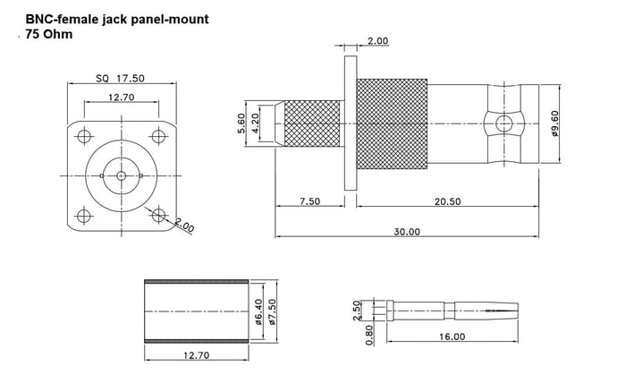
The BNC Connector
The Bayonet Neill Concelman connector is a miniature radio frequency connector with quick connect/disconnect functionality that carries a characteristic two-stud bayonet mating mechanism. The eponymous connector was developed by Paul Neill and Carl Concelman from earlier designs in the 1950s. It was initially used for military communications but over time the applications of this connector have diversified to include telecommunications, aerospace, and digital audio and video as described in detail below. It is available in either 50 Ohm or 75 Ohm versions that have slight physical differences.
Physical specifications of the 75 Ohm BNC connector
The BNC connector is mated using a bayonet coupling mechanism. This twist and snap design involves the insertion of the female body, which carries two lugs into the male connector body. The connect is locked in the mated position by a quarter-turn of the coupling nut, making secure mating fast and tool-free. Within the connectors, the mating involves the insertion of a male connector pin into a female receptacle. The connector is rated for at least 500 mating cycles.
The BNC connector body is typically made from machined brass with nickel plating. With the connector, the insulator may be made from Teflon or Delrin. The male conducting pin is made from gold or silver-plated brass and the female receptacle is made from gold-plated phosphor bronze. The connector also carries a silicone rubber gasket to seal the mated connection.
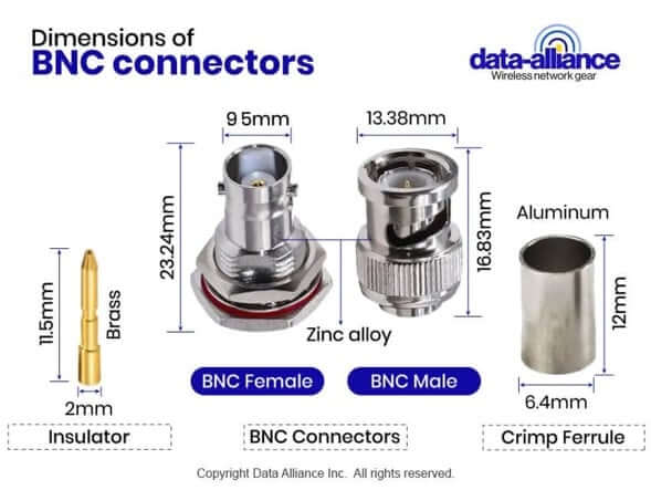
Electrical specifications of the 75 Ohm BNC connector
- The 75 Ohm BNC connector often has a maximum frequency of 2 GHz, which is lower than the 50 Ohm version.
- At 1 GHz the VSWR is 1.05.
- It has a working voltage of 500 Volts.
- It has a withstanding voltage of 1500 Volts.
Precision 75 Ohm BNC connectors differ internally from 50 Ohm versions. The dielectric geometry is optimized to maintain consistent impedance through the connector interface. Using a 50 Ohm connector on a 75 Ohm cable introduces discontinuities that increase return loss and reduce maximum transmission distance.
Future-Proofing Installations
Emerging standards such as 6G-SDI (5.94 Gbps) and 12G-SDI (11.88 Gbps) require even stricter return loss and attenuation performance. Selecting higher-grade 75 Ohm coaxial cable today can improve long-term system scalability.
In conclusion
Professional SDI video transmission demands precision 75 Ohm cable assemblies engineered for high data rate digital signals.
Whether using RG59 for studio installations, RG6 for extended runs, or RG179 for compact interconnects, maintaining impedance integrity and minimizing attenuation is critical for 3G-SDI and HD-SDI performance.
Data Alliance provides high-quality, SMPTE-compliant 75 Ohm BNC cable assemblies with both standard and custom configurations, engineered to meet the demanding requirements of broadcast, surveillance, industrial, and defense applications.
Our technical team assists with cable selection, attenuation calculation, connector matching, and system optimization to ensure reliable, low-latency digital video transmission.
For professional-grade BNC cable assemblies and expert RF/video support, visit:
LEARN MORE:
- BNC cables and adapters
- RG59 Coax for BNC Cables: Best for CCTV: 75 Ohm
- BNC Cables 50 Ohm & 75 Ohm Distinctions, Applications, Connectors
FAQs
What is the difference between 50 Ohm and 75 Ohm BNC cables for video?
75 Ohm BNC cables are designed specifically for video transmission systems such as HD-SDI and 3G-SDI. They maintain the correct impedance required by SMPTE standards. Using a 50 Ohm connector or cable in a 75 Ohm video system creates impedance mismatch, which can cause signal reflections, increased jitter, degraded eye patterns, and reduced transmission distance. For professional SDI installations, true 75 Ohm cable assemblies are required.
Which coaxial cable is best for 3G-SDI applications?
For 3G-SDI (2.97 Gbps), RG59 is typically preferred for medium-length runs due to its lower attenuation. RG6 may be used for longer distances, while RG179 is best suited for short patch cables or compact rack interconnects. The optimal choice depends on run length, installation environment, and system equalization capability. Data Alliance technical support can assist with cable selection based on your specific requirements.
How far can a 3G-SDI signal travel over RG59 or RG179?
Typical industry guidelines are:
- RG59: approximately 70–100 meters (application dependent)
- RG6: approximately 100–140 meters
- RG179: typically under 50 meters
Actual maximum distance depends on cable quality, connector precision, attenuation characteristics, and the use of cable equalizers or reclockers.
Why is maintaining 75 Ohm impedance critical in SDI systems?
SDI signals operate at high data rates and are sensitive to impedance discontinuities. Any mismatch between the cable and connectors can cause reflections, return loss issues, and increased jitter. Maintaining consistent 75 Ohm impedance throughout the signal path ensures optimal signal integrity, reduced distortion, and compliance with SMPTE 424M specifications.
What causes jitter in HD-SDI and 3G-SDI systems?
Jitter refers to timing deviations in digital signal transitions. Common causes include:
- Impedance mismatches
- Poor cable quality
- Excessive cable length
- Improper termination
- High attenuation at critical frequencies
High-quality 75 Ohm BNC cable assemblies minimize deterministic jitter by preserving signal integrity and reducing reflections.
Can BNC cable assemblies be customized for OEM or industrial applications?
Yes. Data Alliance offers both standard and custom BNC cable assemblies, including:
- RG59, RG6, and RG179 options
- Precision 75 Ohm BNC male and female connectors
- Right-angle and bulkhead configurations
- Double-shielded and low-loss variants
- Custom lengths and pre-terminated assemblies
These solutions support broadcast studios, surveillance integrators, defense systems, and OEM video equipment manufacturers.
How can I test the performance of a BNC cable for SDI video?
Cable performance can be evaluated using an oscilloscope to measure:
- Signal amplitude
- Overshoot and undershoot
- Rise and fall time
- Waveform integrity
Advanced testing may include impedance verification, VSWR, insertion loss, and return loss measurements. Ensuring proper crimping with calibrated tools and using precision 75 Ohm connectors are critical to long-term reliability.