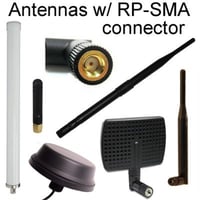
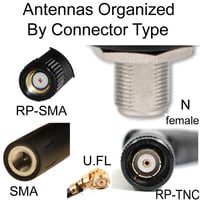
Many GPS antennas have SMA-male connectors or antenna cables to SMA-male connectors

Global Positioning System or GPS antenna cables are lengths of coaxial cable that are specifically used to conduct GPS signals from a GPS antenna to a downstream GPS radio receiver with minimal loss or change. It is a critical component for utilizing the proprietary satellite radio navigation system that is created and owned by the United States Government and can be used to access the locating, navigation, and time functions of the system. The cable is, therefore, necessary for satellite communication between Space and User segments of GPS. Data received by the GPS antenna is transmitted down the cable to a GPS receiver. This satellite navigation device has the software capabilities and drivers to extract the data from the satellite system and display it in an accessible format.

A GPS cable is terminated with a class of radio frequency connector that is compatible with the antenna connector and capable of making a competent mechanical and electrical connection. Cables may be used to connect an external GPS antenna to a GPS device or an internal GPS antenna within a device. They may also be required for connection of a Low Noise Amplifier (LNA) as explained below.

The type of cable used as a GPS cable is critical to the performance of the cable assembly with specific types of coax that is manufactured to be low loss being preferable. The nature of the GPS signal, explored below, means that GPS cable lengths should be kept as low loss as possible. This is achieved in several ways, in particular by doubling the shielding of the coaxial cable and keeping the cable's length short.

The selection of GPS cables provided here is manufactured to the highest standards of quality and provenance. All materials and fabrication of our GPS cables are compliant with the EU Restriction of Hazardous Substances (RoHS) legislation and conflict minerals legislation such as the Dodd-Frank Act (2010) and the Conflict Minerals Regulation (2020).

About GPS

What is GPS?

The Global Positioning System is the world’s first and foremost satellite-based radio navigation system. It was devised by the United States Department of Defense in the 1970s and was a novel and ambitious project. Over the following 20 years, the US launched and established a constellation of 24 continually orbiting satellites, which has expanded to over 30 in contemporary times. The GPS satellite constellation is used to provide precision geolocation and chronological data that can be used for both military and civilian purposes. This is done using a continual satellite broadcast from the orbiting satellites. Access to the transmitted signal was initially restricted to the US military, but since 2000, available to all who can acquire and utilize the signal with a compatible device that has an unobstructed line of sight with the sky. The potential for GPS to be selectively degraded or suspended at any time has been retained by the US Government.

How GPS works

GPS uses 24 of the orbiting satellites, which have been positioned in a medium Earth orbit so that a minimum of 4 satellites will be visible to receivers from any point on the Earth. Each satellite encircles the Earth twice in 24 hours traveling at speeds more than 8,000 miles (12,875 kilometers) per hour. Every orbiting satellite in the constellation continually transmits a signal that encodes specific time and positional data using synchronized atomic clocks that are on-board the satellites. These broadcasts are continually monitored and corrected where necessary by the United States Space Force via their extensive network of command and control centers. The key components of the GPS signal include:

  1. A Pseudorandom noise (PRN) code is a unique binary sequence that is used to identify the transmitting satellite. The PRN is selected to prevent interference between multiple GPS satellite signals, and functions as a type of spreading code that increases the bandwidth of the GPS signal.
  2. Ephemeris Data provides information on the health status of the broadcasting satellite as well as specific data on the accuracy of the satellite, the week number, the age of transmitted data, and the time. It remains valid for computation purposes for up to two hours from its broadcast, known as Time of Ephemeris (ToE).
  3. Almanac Data provides supplementary position and location data which reports on the constellation as a whole. This data is valid for up to 90 days and may be used by GPS receivers to shorten the time to first fix.

The PRN is the identifying component with ephemerides and almanac data providing the radio navigation portion of the satellite message. Downloading the entire message can take several minutes though receivers can shorten this time by relying on the ephemeris data only. The GPS broadcast signal is used by GPS receivers to capture the Time of arrival (TOA) and the Time of flight (TOF). By knowing the time at which the signal arrived and the position, direction of travel, and speed of the transmitting satellites, a plot can be made of the course of the satellite in relation to the receiver’s position on the Earth.

Frequency bands used by GPS

GPS satellite signals are sub-2 GHz signals that use a band of the radio spectrum known as the L-band. The Institute of Electrical and Electronics Engineers (IEEE) has designated the L-band which spans 1 to 2 GHz and is primarily used for aerospace and satellite communication. L-band frequency signals are advantageous as they are capable of penetrating the ionosphere, atmospheric cloud, fog, and precipitation efficiently without the need for an unwieldy beam antenna to receive signals. They main L-band frequencies used by civilian access GPS are:

  • L1 operates at 1575.42 MHz and is 15.345 MHz wide.
  • L2 operates at 1227.60 MHz and has a channel width of 11 MHz.
  • L5 operates at 1176.45 MHz with a bandwidth of 12.5 MHz.

The frequencies used are directly proportional to the default L-band frequency of the atomic clock carried by the orbiting satellites. They provide adequate bandwidth for not only the clock data but also encoding of the PRN codes, ephemeris data, and almanac data onto the carrier signal. Depending on the GPS antenna used one, two, or all three frequencies can be received for fast signal acquisition and the shortest possible time to first fix.

GPS antenna cables:  Key Points

The choice of GPS antenna cable is critical to the performance of a GPS antenna and receiver because of several notable weaknesses in a system that is reliant on receiving signals that have an extraterrestrial origin. By the time the GPS signal has penetrated all the layers of the Earth’s atmosphere to get to a receiver, a significant proportion of the electromagnetic energy has been absorbed meaning that the signal received is already a weakened one. Key challenges encountered with GPS signals include:

  1. GPS multipath interference is a commonly encountered problem that will prolong the time taken for a GPS device to acquire a fix. This interference is caused by the reflection and scattering of the GPS signal off buildings, vegetation, or other natural or man-made structures. This leads to the generation of multiple alternate reflected versions of the signal that arrive at the receiving antenna with delay and can fade or corrupt the overall signal leading to miscalculations of position.
  2. Poor weather can lead to deterioration of the GPS signal, despite its reliable penetration. The performance of an outdoor GPS antenna can be compromised by build-ups of ice and snow and particularly dense precipitation and dense fog can delay the acquisition of a signal and the time to first fix.
  3. Urban areas have a poor line of sight for GPS antennas and the target satellites due to the density of buildings which reduce exposure to open sky. Poor visibility means that the device will experience positional drift and poor accuracy. Built-up areas also cause more multipath effects due to the reflection of the signal off dense building materials and surfaces like concrete.
  4. Indoor environments render GPS ineffective as they are enclosed and have no exposure to the satellite signal. By the time a signal penetrates a building, it is so attenuated that it will be unable to be utilized.

Quality GPS cables and antennas are essential for GPS devices that perform properly

These challenges mean that the receiving antenna and radio equipment used for GPS needs to be efficient at acquiring and relaying the GPS signal. Also, optimal battery or mains power will be needed due to the energy consumption required for GPS devices and the front-end software used for mapping must be accurate. A high-quality GPS cable is vital to keep the loss of signal to an absolute minimum for the correct performance of this radio frequency circuit.

Antennas used for GPS must be efficient 50 Ohm impedance omnidirectional antennas which have right-handed circular polarization (RHCP) which matches the polarization of the GPS signal and allows the antenna to receive the signal at any point from zenith to horizon. GPS antennas are usually high gain, with legal limits specified by the Federal Communications Commission (FCC). When paired with well-matched coaxial cable transmission lines these antennas efficiently convert at least 50% of the electromagnetic energy they receive into radiated power with a Voltage Standing Wave Ratio (VSWR) that is kept as low as possible.

Best coaxial cable for GPS cable assembly

  • The best coaxial cable for GPS is a low loss coaxial cable which has reduced signal loss or attenuation along its length at the L-band frequencies used by GPS.

The unique structure of coaxial cable makes it the most efficient means of transferring GPS signals from source to termination. Its dual outer and inner conductors protect the electromagnetic energy travelling along the line from outside interference and keep the transferred radio frequency energy within the line. The type of coaxial cable selected for use as a GPS antenna cable will determine the radio frequency connectors needed and the electrical specifications for the entire assembly must be precisely matched to keep losses or variance in the overall assembly as low as possible.

Within the upper frequency limit (the cut-off frequency) of a GPS cable, radio frequency signals travel along its length in Transversal Electric and Magnetic (TEM) field mode, with the electrical and magnetic fields at right angles to each other and the axis of the cable. The limits of the cable will be determined by diameter of the cable with smaller diameter GPS antenna cable tolerating higher frequencies. This, however, has to be balanced with the attenuation experienced at higher frequencies due to the dielectric loss and the skin effect.

GPS signal loss via antenna cables

Attenuation is the amount of radio frequency energy that is lost as a signal is transmitted along a length of cable. The losses are usually to thermal dissipation, skin effect, leakage through poor shielding of the cable, and dielectric losses as well as a proportion of signal that may be reflected due to discontinuities in the line. At frequencies under 10 GHz, such as the L-band frequencies used by GPS, conductor losses are the main contributor to signal losses.

Shielding is key to the performance of GPS antenna cable

Shielding protects GPS antenna cable from the radiative losses that can compromise the function of the assembly. Though a 100% shielded line is difficult to achieve, a well-shielded cable will maintain the electromagnetic fields within the cable and keep radiative losses to a minimum. Leaked radio frequency energy not only diminishes signal strength and quality but also can be a source of interference. The combination of a fully closed dielectric layer, copper braided and foil shield layers will minimize the penetration of unwanted electromagnetic energy through to the outer layers of the cable and also the rejection of interference from the environment surrounding the cable. Cables with good shielding effectiveness combine shielding mechanisms (for example a braided layer with an inner foil shield) for maximum coverage against signal loss.

LMR 100 GPS antenna cable

LMR 100 or equivalent high-quality coaxial cable delivers market-leading performance for GPS antenna cable. This semi-flexible mini coaxial cable is known for its superb performance and exceptional low loss and therefore is routinely used in GPS cable assemblies. The physical and electrical specifications of this cable detailed below underpin its utility for GPS connectivity.

Physical features and specifications of LMR 100 GPS antenna cable

LMR 100 has a structure that is comparable to most coax cables with key features that enhance its performance as a low loss cable. The diameter of LMR 100 is 0.11 inches or (2.79mm) and the cable is known for its flexibility, meaning it can be readily routed without risk of damage. This reliable cable is also weather and UV resistant with longevity spanning decades, making it a good choice for GPS antenna installation.

Its solid bare copper-clad steel (BCCS) center conductor has high conductivity. Surrounding the conductor, a polyethylene (PE) dielectric enhances the electrical performance of the cable and remains resistant to water and chemical solvents. The dielectric layer is surrounded by unbounded aluminum tape and a tinned copper outer braid which is covered with an outer plastic jacket that is usually PVC or polyethylene.

The importance of double shielding GPS antenna cables

The double-shielded design of this cable is a premium feature with the combination of foil and braid especially advantageous in reducing GPS signal loss, especially radiative losses from the skin effect at the center conductor. Its shielding effectiveness exceeds 90 decibels. Aluminum mylar foil tape completely encloses the dielectric conferring 100% coverage that is resistant to cracking when the cable is flexed. The tinned copper braid shield is tightly braided with at least 95% coverage. This quality dense braid has a beneficial grounding effect.

Electrical specification of LMR 100 GPS antenna coax cable

This 50 Ohm coax delivers robust performance at the L-band frequencies with a frequency limit of over 60 GHz. The materials and fabrication of this GPS cable make it able to retain current within the cable, reflected in its capacitance of 30.8 pF/ft (100.1pF/m). It has an induction of 0.077uH/ft (0.25 uH/m). This is a measure of the cable's tendency to withstand conducted current and related to the impedance of the cable. Its BCCS core is highly conductive and the velocity of propagation (Vp), expressed as a percentage of the speed of light is 66%. Its copper-coated steel core can also tolerate voltages of up to 500 Volts.

Key connectors used on GPS antenna cable assemblies

The choice of connector used in the GPS antenna cable should also minimize signal losses, reflections and dispersion. A perfectly-matched homogenous connector does not exist in reality but many good connector choices are available in pre-assembled GPS antenna cables which deliver a good performance. The coaxial connectors that are commonly used all have an impedance of 50 Ohm with a frequency range that fully accommodates L-band connectivity. Most connectors also keep VSWR, insertion loss, and radio frequency leakage as low as possible, while providing a high number of mating cycles for the longevity of the assembly. Miniature or micro-miniature connectors may be used to connect a GPS antenna directly to a PCB via a micro-miniature pigtail adapter which is kept as short as possible.

Common connectors used in an LMR 100 GPS antenna cable assembly include:

Frequently asked questions

How do I install a GPS antenna?

Taking care to properly mount your GPS antenna and cable will ensure that it functions as it should. Here are some key steps for installing your GPS antenna correctly:

  1. How to correctly locate a GPS antenna

For GPS antennas to work properly they require unobstructed exposure to the open sky so they can be visible to as many satellites as possible. Mount the antenna as high as possible, on the roof of a building or car, clear of other major structures that will interfere with the line of the horizon. A suitable pole or bracket mounting system can be used for buildings and magnetic mounts or through-hole mounting systems are commonly used for vehicles. When locating the antenna, other antenna installations should be avoided, as well as environments where the antenna or its cable may become immersed in standing water or covered by vegetation or snow.

  1. Connecting the GPS cable to the antenna

The coaxial cable should be attached to both the antenna and other ancillary products in the GPS, including lighting arrestors and LNAs. Several suitable indoor and outdoor GPS antenna cables and connector adapters may be needed for the various radio components. Cable lengths should be as short as possible and ideally, adapters should be avoided as they increase discontinuities in the setup. The antenna cable can be supported with cable hangers or installed in a sealed conduit that can accommodate its connectors.

  1. Evaluate GPS system performance and adjust the installation if necessary

All components in the assembly may require adjustment if the performance of the GPS antenna installation is poor. Reposition the antenna and its mount if needed. Adjusting cable length can make a significant difference to the performance of the overall system. Once the optimal performance of the GPS antenna is attained, the system can be properly waterproofed with coaxial cable tape or dielectric grease to seal and protect any exposed connections.

Do these cables work with other satellite navigation systems?

The GPS antenna cables available above can be used for the competent provision of connectivity for any Global Navigation Satellite System (GNSS) including:

  • GLONASS (Russia)
  • BeiDou (China)
  • Galileo (European Union)
  • Quasi-Zenith (Japan)

These alternate satellite navigation systems all work on a similar basis to GPS but differ in the numbers of satellites and orbital planes used.

Can RG 174 be used as a GPS cable?

RG 174 is a flexible coaxial cable which is of similar diameter to LMR 100. However, it is different from LMR 100-type cables as it is only single shielded, has a stranded inner conductor, and a lower frequency limit. LMR 100 is a better choice for GPS antenna cabling as it has lower attenuation in dB/ft at every frequency.

What is an LNA?

A Low Noise Amplifier (LNA) is an electronic device that can be installed in-line to amplify very low power GPS signals. A generic amplifier will amplify both the received signal and any interference or noise present. A low noise amplifier is able to strip the noise from the signal, preserving an optimal signal to noise ratio (SNR).

In conclusion

The selection of a GPS cable is critical to the performance of a GPS antenna and receiver. GPS antenna cables should be chosen for their quality of shielding, with a double-shielded coaxial cable like LMR 100 delivering the lowest signal loss. GPS antenna cable assemblies feature high-quality robust connectors that will withstand repeated mating cycles and outdoor conditions.

LEARN MORE:

GPS antenna cables

Many GPS antennas have SMA-male connectors or antenna cables to SMA-male connectors

Global Positioning System or GPS antenna cables are lengths of coaxial cable that are specifically used to conduct GPS signals from a GPS antenna to a downstream GPS radio receiver with minimal loss or change. It is a critical component for utilizing the proprietary satellite radio navigation system that is created and owned by the United States Government and can be used to access the locating, navigation, and time functions of the system. The cable is, therefore, necessary for satellite communication between Space and User segments of GPS. Data received by the GPS antenna is transmitted down the cable to a GPS receiver. This satellite navigation device has the software capabilities and drivers to extract the data from the satellite system and display it in an accessible format.

A GPS cable is terminated with a class of radio frequency connector that is compatible with the antenna connector and capable of making a competent mechanical and electrical connection. Cables may be used to connect an external GPS antenna to a GPS device or an internal GPS antenna within a device. They may also be required for connection of a Low Noise Amplifier (LNA) as explained below.

The type of cable used as a GPS cable is critical to the performance of the cable assembly with specific types of coax that is manufactured to be low loss being preferable. The nature of the GPS signal, explored below, means that GPS cable lengths should be kept as low loss as possible. This is achieved in several ways, in particular by doubling the shielding of the coaxial cable and keeping the cable's length short.

The selection of GPS cables provided here is manufactured to the highest standards of quality and provenance. All materials and fabrication of our GPS cables are compliant with the EU Restriction of Hazardous Substances (RoHS) legislation and conflict minerals legislation such as the Dodd-Frank Act (2010) and the Conflict Minerals Regulation (2020).

About GPS

What is GPS?

The Global Positioning System is the world’s first and foremost satellite-based radio navigation system. It was devised by the United States Department of Defense in the 1970s and was a novel and ambitious project. Over the following 20 years, the US launched and established a constellation of 24 continually orbiting satellites, which has expanded to over 30 in contemporary times. The GPS satellite constellation is used to provide precision geolocation and chronological data that can be used for both military and civilian purposes. This is done using a continual satellite broadcast from the orbiting satellites. Access to the transmitted signal was initially restricted to the US military, but since 2000, available to all who can acquire and utilize the signal with a compatible device that has an unobstructed line of sight with the sky. The potential for GPS to be selectively degraded or suspended at any time has been retained by the US Government.

How GPS works

GPS uses 24 of the orbiting satellites, which have been positioned in a medium Earth orbit so that a minimum of 4 satellites will be visible to receivers from any point on the Earth. Each satellite encircles the Earth twice in 24 hours traveling at speeds more than 8,000 miles (12,875 kilometers) per hour. Every orbiting satellite in the constellation continually transmits a signal that encodes specific time and positional data using synchronized atomic clocks that are on-board the satellites. These broadcasts are continually monitored and corrected where necessary by the United States Space Force via their extensive network of command and control centers. The key components of the GPS signal include:

  1. A Pseudorandom noise (PRN) code is a unique binary sequence that is used to identify the transmitting satellite. The PRN is selected to prevent interference between multiple GPS satellite signals, and functions as a type of spreading code that increases the bandwidth of the GPS signal.
  2. Ephemeris Data provides information on the health status of the broadcasting satellite as well as specific data on the accuracy of the satellite, the week number, the age of transmitted data, and the time. It remains valid for computation purposes for up to two hours from its broadcast, known as Time of Ephemeris (ToE).
  3. Almanac Data provides supplementary position and location data which reports on the constellation as a whole. This data is valid for up to 90 days and may be used by GPS receivers to shorten the time to first fix.

The PRN is the identifying component with ephemerides and almanac data providing the radio navigation portion of the satellite message. Downloading the entire message can take several minutes though receivers can shorten this time by relying on the ephemeris data only. The GPS broadcast signal is used by GPS receivers to capture the Time of arrival (TOA) and the Time of flight (TOF). By knowing the time at which the signal arrived and the position, direction of travel, and speed of the transmitting satellites, a plot can be made of the course of the satellite in relation to the receiver’s position on the Earth.

Frequency bands used by GPS

GPS satellite signals are sub-2 GHz signals that use a band of the radio spectrum known as the L-band. The Institute of Electrical and Electronics Engineers (IEEE) has designated the L-band which spans 1 to 2 GHz and is primarily used for aerospace and satellite communication. L-band frequency signals are advantageous as they are capable of penetrating the ionosphere, atmospheric cloud, fog, and precipitation efficiently without the need for an unwieldy beam antenna to receive signals. They main L-band frequencies used by civilian access GPS are:

  • L1 operates at 1575.42 MHz and is 15.345 MHz wide.
  • L2 operates at 1227.60 MHz and has a channel width of 11 MHz.
  • L5 operates at 1176.45 MHz with a bandwidth of 12.5 MHz.

The frequencies used are directly proportional to the default L-band frequency of the atomic clock carried by the orbiting satellites. They provide adequate bandwidth for not only the clock data but also encoding of the PRN codes, ephemeris data, and almanac data onto the carrier signal. Depending on the GPS antenna used one, two, or all three frequencies can be received for fast signal acquisition and the shortest possible time to first fix.

GPS antenna cables:  Key Points

The choice of GPS antenna cable is critical to the performance of a GPS antenna and receiver because of several notable weaknesses in a system that is reliant on receiving signals that have an extraterrestrial origin. By the time the GPS signal has penetrated all the layers of the Earth’s atmosphere to get to a receiver, a significant proportion of the electromagnetic energy has been absorbed meaning that the signal received is already a weakened one. Key challenges encountered with GPS signals include:

  1. GPS multipath interference is a commonly encountered problem that will prolong the time taken for a GPS device to acquire a fix. This interference is caused by the reflection and scattering of the GPS signal off buildings, vegetation, or other natural or man-made structures. This leads to the generation of multiple alternate reflected versions of the signal that arrive at the receiving antenna with delay and can fade or corrupt the overall signal leading to miscalculations of position.
  2. Poor weather can lead to deterioration of the GPS signal, despite its reliable penetration. The performance of an outdoor GPS antenna can be compromised by build-ups of ice and snow and particularly dense precipitation and dense fog can delay the acquisition of a signal and the time to first fix.
  3. Urban areas have a poor line of sight for GPS antennas and the target satellites due to the density of buildings which reduce exposure to open sky. Poor visibility means that the device will experience positional drift and poor accuracy. Built-up areas also cause more multipath effects due to the reflection of the signal off dense building materials and surfaces like concrete.
  4. Indoor environments render GPS ineffective as they are enclosed and have no exposure to the satellite signal. By the time a signal penetrates a building, it is so attenuated that it will be unable to be utilized.

Quality GPS cables and antennas are essential for GPS devices that perform properly

These challenges mean that the receiving antenna and radio equipment used for GPS needs to be efficient at acquiring and relaying the GPS signal. Also, optimal battery or mains power will be needed due to the energy consumption required for GPS devices and the front-end software used for mapping must be accurate. A high-quality GPS cable is vital to keep the loss of signal to an absolute minimum for the correct performance of this radio frequency circuit.

Antennas used for GPS must be efficient 50 Ohm impedance omnidirectional antennas which have right-handed circular polarization (RHCP) which matches the polarization of the GPS signal and allows the antenna to receive the signal at any point from zenith to horizon. GPS antennas are usually high gain, with legal limits specified by the Federal Communications Commission (FCC). When paired with well-matched coaxial cable transmission lines these antennas efficiently convert at least 50% of the electromagnetic energy they receive into radiated power with a Voltage Standing Wave Ratio (VSWR) that is kept as low as possible.

Best coaxial cable for GPS cable assembly

  • The best coaxial cable for GPS is a low loss coaxial cable which has reduced signal loss or attenuation along its length at the L-band frequencies used by GPS.

The unique structure of coaxial cable makes it the most efficient means of transferring GPS signals from source to termination. Its dual outer and inner conductors protect the electromagnetic energy travelling along the line from outside interference and keep the transferred radio frequency energy within the line. The type of coaxial cable selected for use as a GPS antenna cable will determine the radio frequency connectors needed and the electrical specifications for the entire assembly must be precisely matched to keep losses or variance in the overall assembly as low as possible.

Within the upper frequency limit (the cut-off frequency) of a GPS cable, radio frequency signals travel along its length in Transversal Electric and Magnetic (TEM) field mode, with the electrical and magnetic fields at right angles to each other and the axis of the cable. The limits of the cable will be determined by diameter of the cable with smaller diameter GPS antenna cable tolerating higher frequencies. This, however, has to be balanced with the attenuation experienced at higher frequencies due to the dielectric loss and the skin effect.

GPS signal loss via antenna cables

Attenuation is the amount of radio frequency energy that is lost as a signal is transmitted along a length of cable. The losses are usually to thermal dissipation, skin effect, leakage through poor shielding of the cable, and dielectric losses as well as a proportion of signal that may be reflected due to discontinuities in the line. At frequencies under 10 GHz, such as the L-band frequencies used by GPS, conductor losses are the main contributor to signal losses.

Shielding is key to the performance of GPS antenna cable

Shielding protects GPS antenna cable from the radiative losses that can compromise the function of the assembly. Though a 100% shielded line is difficult to achieve, a well-shielded cable will maintain the electromagnetic fields within the cable and keep radiative losses to a minimum. Leaked radio frequency energy not only diminishes signal strength and quality but also can be a source of interference. The combination of a fully closed dielectric layer, copper braided and foil shield layers will minimize the penetration of unwanted electromagnetic energy through to the outer layers of the cable and also the rejection of interference from the environment surrounding the cable. Cables with good shielding effectiveness combine shielding mechanisms (for example a braided layer with an inner foil shield) for maximum coverage against signal loss.

LMR 100 GPS antenna cable

LMR 100 or equivalent high-quality coaxial cable delivers market-leading performance for GPS antenna cable. This semi-flexible mini coaxial cable is known for its superb performance and exceptional low loss and therefore is routinely used in GPS cable assemblies. The physical and electrical specifications of this cable detailed below underpin its utility for GPS connectivity.

Physical features and specifications of LMR 100 GPS antenna cable

LMR 100 has a structure that is comparable to most coax cables with key features that enhance its performance as a low loss cable. The diameter of LMR 100 is 0.11 inches or (2.79mm) and the cable is known for its flexibility, meaning it can be readily routed without risk of damage. This reliable cable is also weather and UV resistant with longevity spanning decades, making it a good choice for GPS antenna installation.

Its solid bare copper-clad steel (BCCS) center conductor has high conductivity. Surrounding the conductor, a polyethylene (PE) dielectric enhances the electrical performance of the cable and remains resistant to water and chemical solvents. The dielectric layer is surrounded by unbounded aluminum tape and a tinned copper outer braid which is covered with an outer plastic jacket that is usually PVC or polyethylene.

The importance of double shielding GPS antenna cables

The double-shielded design of this cable is a premium feature with the combination of foil and braid especially advantageous in reducing GPS signal loss, especially radiative losses from the skin effect at the center conductor. Its shielding effectiveness exceeds 90 decibels. Aluminum mylar foil tape completely encloses the dielectric conferring 100% coverage that is resistant to cracking when the cable is flexed. The tinned copper braid shield is tightly braided with at least 95% coverage. This quality dense braid has a beneficial grounding effect.

Electrical specification of LMR 100 GPS antenna coax cable

This 50 Ohm coax delivers robust performance at the L-band frequencies with a frequency limit of over 60 GHz. The materials and fabrication of this GPS cable make it able to retain current within the cable, reflected in its capacitance of 30.8 pF/ft (100.1pF/m). It has an induction of 0.077uH/ft (0.25 uH/m). This is a measure of the cable's tendency to withstand conducted current and related to the impedance of the cable. Its BCCS core is highly conductive and the velocity of propagation (Vp), expressed as a percentage of the speed of light is 66%. Its copper-coated steel core can also tolerate voltages of up to 500 Volts.

Key connectors used on GPS antenna cable assemblies

The choice of connector used in the GPS antenna cable should also minimize signal losses, reflections and dispersion. A perfectly-matched homogenous connector does not exist in reality but many good connector choices are available in pre-assembled GPS antenna cables which deliver a good performance. The coaxial connectors that are commonly used all have an impedance of 50 Ohm with a frequency range that fully accommodates L-band connectivity. Most connectors also keep VSWR, insertion loss, and radio frequency leakage as low as possible, while providing a high number of mating cycles for the longevity of the assembly. Miniature or micro-miniature connectors may be used to connect a GPS antenna directly to a PCB via a micro-miniature pigtail adapter which is kept as short as possible.

Common connectors used in an LMR 100 GPS antenna cable assembly include:

Frequently asked questions

How do I install a GPS antenna?

Taking care to properly mount your GPS antenna and cable will ensure that it functions as it should. Here are some key steps for installing your GPS antenna correctly:

  1. How to correctly locate a GPS antenna

For GPS antennas to work properly they require unobstructed exposure to the open sky so they can be visible to as many satellites as possible. Mount the antenna as high as possible, on the roof of a building or car, clear of other major structures that will interfere with the line of the horizon. A suitable pole or bracket mounting system can be used for buildings and magnetic mounts or through-hole mounting systems are commonly used for vehicles. When locating the antenna, other antenna installations should be avoided, as well as environments where the antenna or its cable may become immersed in standing water or covered by vegetation or snow.

  1. Connecting the GPS cable to the antenna

The coaxial cable should be attached to both the antenna and other ancillary products in the GPS, including lighting arrestors and LNAs. Several suitable indoor and outdoor GPS antenna cables and connector adapters may be needed for the various radio components. Cable lengths should be as short as possible and ideally, adapters should be avoided as they increase discontinuities in the setup. The antenna cable can be supported with cable hangers or installed in a sealed conduit that can accommodate its connectors.

  1. Evaluate GPS system performance and adjust the installation if necessary

All components in the assembly may require adjustment if the performance of the GPS antenna installation is poor. Reposition the antenna and its mount if needed. Adjusting cable length can make a significant difference to the performance of the overall system. Once the optimal performance of the GPS antenna is attained, the system can be properly waterproofed with coaxial cable tape or dielectric grease to seal and protect any exposed connections.

Do these cables work with other satellite navigation systems?

The GPS antenna cables available above can be used for the competent provision of connectivity for any Global Navigation Satellite System (GNSS) including:

  • GLONASS (Russia)
  • BeiDou (China)
  • Galileo (European Union)
  • Quasi-Zenith (Japan)

These alternate satellite navigation systems all work on a similar basis to GPS but differ in the numbers of satellites and orbital planes used.

Can RG 174 be used as a GPS cable?

RG 174 is a flexible coaxial cable which is of similar diameter to LMR 100. However, it is different from LMR 100-type cables as it is only single shielded, has a stranded inner conductor, and a lower frequency limit. LMR 100 is a better choice for GPS antenna cabling as it has lower attenuation in dB/ft at every frequency.

What is an LNA?

A Low Noise Amplifier (LNA) is an electronic device that can be installed in-line to amplify very low power GPS signals. A generic amplifier will amplify both the received signal and any interference or noise present. A low noise amplifier is able to strip the noise from the signal, preserving an optimal signal to noise ratio (SNR).

In conclusion

The selection of a GPS cable is critical to the performance of a GPS antenna and receiver. GPS antenna cables should be chosen for their quality of shielding, with a double-shielded coaxial cable like LMR 100 delivering the lowest signal loss. GPS antenna cable assemblies feature high-quality robust connectors that will withstand repeated mating cycles and outdoor conditions.

LEARN MORE: