Definitions: Wireless & WiFi terms
Access Points & Bridges: Definitions
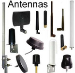
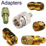
Coaxial Antenna Cable Assemblies & Connectors: Definitions of types
Fresnel Zone: An electromagnetic phenomenon, in which light waves or radio signals get diffracted or bent from solid objects near their path. The radio waves reflecting off the objects may arrive out of phase with the signals that traveled directly to the receiving antenna thus reducing the power of the received signal. Therefore you have to have more than visual line-of-sight: You need for the fresnel zone to be clear or the obstructions will block part of your throughout - you will have lower rate of through-put.
Signal Strength: RSSI: Received Signal Strength Indication: Measured from 0 to -100, generally, though RSSI has no standard units for all vendors: Generally the higher (closer to 0) the better, and the closer to -100 the worse.
SNR: Signal-to-Noise Ratio and Noise Floor: SNR is not actually a ratio but the difference in decibels between the received signal and the background noise level (noise floor). For example, if a radio (client device) receives a signal of -75 dBm and the noise floor is measured at -90 dBm, the SNR is 15 dB. Data corruption and therefore re-transmissions will occur if the received signal is too close to the noise floor. Re-transmissions adversely affect throughput and latency.
Noise Floor: Use a spectrum analyzer to determine the noise floor: Ubiquiti's AirView spectrum analyzer is built-in to all AirMax equipment: Noise Floor is easily found by looking at the Waterfall View - the legend in the upper right corner: The number to the far-left in this legend is always adjusted to the calculated noise floor (and the high end [right] is fixed at the highest detected power since the start of the session).
MCS: Modulation and Coding Scheme: MCS Index Values: Modulation and Coding Scheme (MCS) Index Values can be used in conjunction with channel width values to allow you to instantly calculate the available data rate of your wireless hardware.
- The MCS index value list gives every combination of "number of spatial streams + modulation type + coding rate" that is possible. In practice the achievable MCS value will depend on a large number of variables, and it may be prudent to run your hardware at a lower MCS value on purpose in order to allow for adequate fade margin in your link.
- The MCS value will only tell you the 'over the air' data rate of a link and not tell you what the actual usable throughput will be. You will need to refer to the documentation of your hardware for this information.
PHY Rate (Link Rate) compared to Throughput (Transfer Speed): Difference between wireless link rate, actual file transfer and web browsing speed:
- The wireless link rate is sometimes called the physical layer (PHY) rate. It is the maximum speed that data can move across a wireless link between a wireless client and a wireless access point or bridge.
- User activities like file transfer and web content browsing happen at the application layer. The rate obtained at the application layer is much lower than the physical layer rate. In fact, a link rate of "300 Mbps" usually corresponds to 50 to 90 Mbps speed on the TCP/UDP layer.

Posted by George Hardesty on 27th Dec 2022


