


Antennas, Antenna Cables, Wireless Products: Technical Articles
Antenna Jacks: U.FL, MHF4, RP-SMA, SMA: Add/Upgrade Antenna to Vastly Increase Range
Table of Contents
Antenna Connector Types: U.FL, MHF4, RP-SMA, SMA | WiFi & LTE Antenna Jacks
Antenna Jacks are radio frequency connectors that are usually fixed on or housed within radio equipment. They facilitate the mechanically and electrically secure connection of an antenna, either via cable or directly to a radio device. When integrated within a radio device, the antenna jack forms a port to receive the compatible antenna connector (plug). They are prevalent in wireless networking, GPS, and cellular devices for the connection of compatible external antennas. An antenna jack may be PCB mounted or panel mounted on devices like routers or base stations. Antenna jacks also used to be a feature on many models of cellular phones, often hidden behind a rubber plug.
- Mini-PCI wireless cards have either MMCX, U.FL, or MHF4. MHF4 is the newest type and is the smallest RF connector. MMCX connectors provide a stronger connection to antennas than U.FL connectors (less signal loss) and MMCX is less fragile than U.FL: UFL connectors are more prone to pop off the miniPCI card.
- Cables with U.FL connectors, MMCX, MHF4 and H.FL connectors enable you to connect any antenna to a miniPCI card
- Mini-PCI wireless cards have either U.FL, MHF4, or MMCX jacks. WiFi routers have RP-SMA jacks.
- Consumer LTE devices have SMA jacks.
Connector Comparison Table
Connector | Common Use | Frequency | Size | Typical Device |
U.FL | Internal WiFi | up to 6 GHz | Ultra-small | Mini-PCI cards |
MHF4 | LTE / IoT modules | up to 6 GHz | Extremely small | M.2 cellular modules |
MMCX | GPS / telecom | up to 6 GHz | Small | GPS receivers |
SMA | Cellular / RF equipment | up to 18 GHz | Medium | LTE routers |
RP-SMA | WiFi routers | up to 6 GHz | Medium | WiFi antennas |
Cable Categories with options for each type: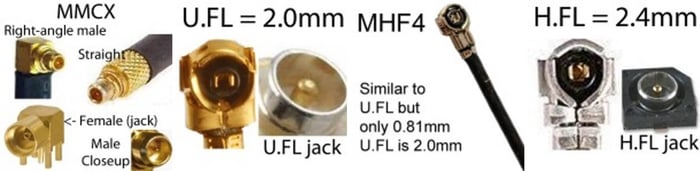
Add or Upgrade an Antenna to Vastly Increase Wireless Range
Antenna Jacks
Antenna jacks are radio-frequency (RF) connectors integrated into wireless devices. They provide a secure electrical and mechanical connection point for attaching an antenna either directly or via a coaxial cable or adapter cable.
When an antenna jack is built into a radio device, it forms a port that accepts a compatible antenna connector (plug). These connectors are commonly used in:
- WiFi routers
- Cellular modems and gateways
- IoT devices
- GPS receivers
- wireless networking equipment
- mini-PCI and M.2 wireless cards
Antenna jacks may be PCB-mounted inside devices or panel-mounted on the device enclosure.
Historically, many cellular phones included external antenna jacks, usually hidden behind a rubber plug.
Increase Wireless Range with an External Antenna
Many wireless devices include small internal antennas. While convenient, these antennas may have limited range and signal strength.
Adding an external antenna through the antenna jack can:
- Greatly improve signal strength
- Extend WiFi or cellular coverage
- Improve data throughput
- Reduce dropped connections
External antennas can also be placed in an optimal location or line-of-sight position, which can dramatically improve wireless performance.
If the distance to a wireless access point is more than about 300 feet, upgrading to a higher-gain external antenna is often recommended.
For example:
- WiFi routers commonly use RP-SMA connectors
- Cellular LTE devices often use SMA connectors
- Internal wireless cards typically use U.FL or MHF4 connectors
Using a pigtail cable adapter allows small internal connectors to connect to larger external antennas.
What is an Antenna Jack?
A jack is the fixed portion of an RF connector pair. It is mounted on the device or PCB and mates with a plug connector attached to a cable or antenna.
Traditionally:
- Jacks are female
- Plugs are male
However, RF connectors sometimes reverse the electrical gender (such as RP-SMA connectors), which can cause confusion.
Common Types of Antenna Jacks
Wireless devices use several RF connector types depending on size, durability, and frequency range.
The most common connectors used in WiFi, cellular, and IoT equipment include:
- U.FL
- MHF4
- MMCX
- H.FL
- SMA
- RP-SMA
These connectors must be matched with the same connector type on the antenna or cable.
U.FL Antenna Jack
The U.FL connector, manufactured by Hirose, is an extremely small RF connector designed for compact wireless devices.
Typical uses include:
- WiFi modules
- Mini-PCI wireless cards
- M.2 WiFi modules
- IoT radio modules
- GPS receivers
Key characteristics:
- Frequency range: DC to 6 GHz
- Mated height: approx. 2 mm
- Impedance: 50 Ohms
- Rated mating cycles: approx. 30
U.FL connectors are typically soldered onto a PCB and used with micro-coax pigtail cables (often 1.13 mm or 1.32 mm coax).
Because the connector is small, it is fragile and not intended for repeated disconnects. For this reason, a U.FL-to-SMA or U.FL-to-RP-SMA pigtail cable is often used to route the connection to a more durable external connector.
See list of all of our articles about U.FL cables and connectors.
MMCX Antenna Jack
MMCX (Micro-Miniature Coaxial) connectors are slightly larger and more durable than U.FL connectors.
They are widely used in:
- Wireless communication equipment
- GPS systems
- Telecommunications equipment
- Embedded radio modules
Key characteristics:
- Frequency range: DC to 6 GHz
- Impedance: 50 ohms
- Rated mating cycles: approx. 500
- Snap-on connection with 360-degree rotation
MMCX connectors provide a stronger and more durable connection than U.FL, making them suitable for applications where cables may be connected and disconnected more frequently.
MHF4 Antenna Jack
The MHF4 connector, developed by IPEX, is one of the smallest RF connectors currently used in wireless devices.
Typical uses include:
- Modern LTE modules
- 5G modules
- Compact IoT radios
- GPS modules
- M.2 wireless cards
Key characteristics:
- Mated height: approx. 1.2 mm
- Frequency range: DC to 6 GHz
- Impedance: 50 ohms
- Rated mating cycles: approx. 30
Because of its extremely small size, the MHF4 connector is commonly used in space-constrained IoT designs.
MHF4 connectors are usually connected to micro-coax pigtail cables that terminate in SMA or RP-SMA connectors for external antennas.
H.FL Antenna Jack
The H.FL connector, also manufactured by Hirose, is another compact RF connector used in wireless devices.
Key characteristics:
- Frequency range: up to 3 GHz
- Impedance: 50 ohms
- Mated height: approx. 3 mm
- Rated mating cycles: approx. 30
Like U.FL and MHF4 connectors, H.FL connectors are typically used with micro-coax pigtail cables to connect to external antennas.
SMA Antenna Jack
The SMA (SubMiniature version A) connector is one of the most common RF connectors used for antennas.
It is widely used in:
- Cellular modems
- LTE routers
- GPS antennas
- Radio equipment
- Wireless test equipment
Key characteristics:
- Frequency range: up to 18 GHz
- Impedance: 50 ohms
- Threaded coupling for secure connection
- Rated mating cycles: approx. 500
SMA connectors provide a robust and reliable threaded connection that performs well in both indoor and outdoor applications.
RP-SMA Antenna Jack
RP-SMA (Reverse Polarity SMA) connectors are commonly used on WiFi routers and wireless adapters.
They look similar to standard SMA connectors but have reversed center pin gender.
Example:
Connector | Center Pin |
SMA Male | Pin |
SMA Female | Socket |
RP-SMA Male | Socket |
RP-SMA Female | Pin |
This design was originally introduced to prevent unauthorized antenna upgrades on consumer WiFi equipment.
Most WiFi routers use RP-SMA female antenna jacks.
Using Pigtail Cables to Connect Antennas
Small RF connectors on circuit boards are often too fragile to support large antennas directly.
For this reason, adapter cables (pigtails) are used.
Example:
- U.FL → RP-SMA cable
- MHF4 → SMA cable
- MMCX → SMA cable
These cables allow:
- Connection to larger antennas
- Mounting connectors on device enclosures
- Protecting fragile PCB connectors from damage
Data-Alliance offers many antenna adapter cables and pigtails for these connector types.
Best Coaxial Cable for Miniature RF Connectors
Micro RF connectors are usually attached to:
Cable length should generally be kept under 150 mm (6 inches) whenever possible to minimize signal loss.
Avoid:
- Sharp bends
- Tight loops
- Routing cables near high-noise electronics
Installing Antenna Jacks on PCBs
- RF connectors mounted on a PCB must maintain proper impedance and grounding.
- Important considerations include:
- Maintain 50-ohm impedance through the RF path
- Keep the VSWR below 2.0
- Position connectors near the edge of the PCB when possible
- Maintain adequate ground plane connections
Edge-mounted SMA connectors typically require five solder points:
- Four ground/mechanical points
- One RF signal connection
These connectors should be securely soldered to prevent mechanical stress.
Why Antenna Jacks Are Important
An antenna jack allows a wireless device to use external antennas with higher gain or directional performance.
Advantages include:
- Extended wireless range
- Improved signal reliability
- Faster data transfer rates
- Flexible antenna placement
External antennas can also be located away from interference sources for improved reception.
Using an external antenna may be done to provide wireless connectivity for the device because an internal antenna is not integrated or to enhance the existing wireless connectivity of the radio device.
Antenna jacks are also advantageous as they provide a means of connecting larger antennas or antennas with specific characteristics (such as directivity) which will provide increased gain for greater coverage and improved data transfer speeds. An external antenna can be located at a distance from the computer or device to which it is attached for better reception. If the distance to the Wireless Access Point's antenna is more than 300 feet, you should consider upgrading your external antenna. Adding an upgraded antenna vastly increases the range of your WiFi router or other WiFi device. Without an upgraded external antenna, you may have issues with the signal fading out sometimes.
Where a larger antenna is connected to a PCB-mounted antenna jack, a pigtail adapter may be used to facilitate the connection of the antenna with a different type of connector and protect the fragile miniature jack from repeated mating cycles which could damage the PCB.
Antenna jacks for installation on Printed Circuit Boards (PCBs)
Attaching an antenna jack to a PCB requires the same consideration and planning that is needed for positioning an embedded antenna. The embedded jacks are usually located in the corners or edges of a PCB with careful management of impedance, antenna trace (of the attached antenna), ground planes, and shielding or isolation of surrounding electronics.
- Impedance should be 50 Ohm between the radio module, antenna jack, PCB trace or coax, and antenna but there is a potential for the impedance of the radio frequency circuit to vary from 50 Ohm in the practical setting. This will require adjustment of antenna impedance to optimize performance at the required transmitting and receiving bands.
- VSWR of the overall circuit should be kept as low as possible, ideally below 2.0.
- If there is a proximity between the connector and other components they may be bi-directional interference between the connector and surrounding circuitry.
- Internal antennas on the PCB will need isolation by distance (at least 20 millimeters from other components if possible) or having different polarizations of the external and embedded antennas.
Installing antenna jacks on PCBs
An antenna jack can be attached to a PCB with solder. Once the position of the jack is planned, melt solder onto the board. If handling a surface mounted miniature jack like the U.FL connector handle it with tweezers and inspect its side and inlet pads which will become points of attachment. These are the points of mechanical and electrical connection and will need to be soldered in. For SMA or RP-SMA edge-mounted jacks they can be slid into place on the PCB. These edge-mounted jacks have 5 points of connection that will need to be soldered in. 4 are mechanical or ground and one is electrical. SMA connectors should be generously soldered as they can be pried off by the attached antenna if they are not firmly fixed. Alternatively, through-hole mounted jacks can be positioned more centrally on a board with greater mechanical stability at the stakes. They will require similar soldering at their 5 points, taking care that good electrical conductivity is created between the connector and the board.
RP-SMA and U.FL antenna jacks for PCBs
RP-SMA and U.FL connectors are commonly attached to PCB to support the connection of external antennas. If the larger RP-SMA jack is integrated within a device it needs to be installed near the edge of the device enclosure. The connector can be secured via a bulkhead. U.FL jacks are designed to be used with a pigtail plug that terminates with a larger connector type (SMA, TNC antenna, N-Type) or antenna. PCB antennas and simple wire antennas can also be attached via a U.FL.
Antenna jacks for mini PCI wireless cards
Miniature antenna jacks are a critical component of PCI and PCI Express (PCIe) cards. Mini-PCI wireless cards carry either U.FL, MHF4, or MMCX jacks. These cards add or improve the wireless networking capability of a computer or laptop and are connected via a port on the computer's motherboard. These cards come complete with multiple external antennas (for spatial diversity) usually connected via RP-SMA jacks.
Integrated Wireless LAN PCIe cards can also have antennas attached via U.FL connectors or equivalent microminiature connectors. The antenna cables usually attach to main and auxiliary U.FL or MHF4 jacks on the card.
Antenna jacks for USB wireless adapters
Antenna jacks can also be added to USB WiFi adapters to allow an external antenna to be attached. If an SMA connector is too fragile, it can be replaced with the soldering-in of a larger connector type like TNC or N-type. Most wireless cards have an RP-SMA (female) antenna jack, for attaching an external antenna to boost your signal. All of the Alfa USB adapters in our site have an RP-SMA female jack.
Things to know
Best coaxial cable for PCB antennas
IPEX MHF4, U.FL, and H.FL connectors are frequently attached to 1.13 and 1.32mm micro coaxial cable for PCB antennas. The cable length should be kept to a minimum (less than 150 millimeters or 5.9 inches) to limit signal loss along with it and it should be well-grounded. Looping or kinking of the cable should be avoided as the transmitted radio frequency energy can create a magnetic field that causes interference. Ideally coax should be isolated from other emitting components in the electronic device.
Use Cases
- Improve LTE Router Signal
If your LTE router has weak signal strength, upgrading to a high-gain external SMA antenna can dramatically improve connectivity.
- Connect External Antenna to M.2 Cellular Module
Many LTE modules use MHF4 connectors, which require MHF4-to-SMA adapter cables to connect external antennas.
- Upgrade WiFi Router Antennas
Most WiFi routers use RP-SMA connectors, allowing higher-gain antennas to be installed to improve coverage.
Conclusion
Antenna jacks are critical components in wireless devices, enabling the connection of external antennas for improved wireless performance.
Common RF connectors such as U.FL, MHF4, MMCX, SMA, and RP-SMA allow wireless equipment to connect to a wide range of antenna types.
By selecting the correct connector and using appropriate adapter cables or pigtails, wireless devices can achieve greater range, improved signal quality, and more reliable connectivity.
FAQs
What is an antenna jack and what does it do?
An antenna jack is a radio frequency (RF) connector fixed on or within radio equipment that allows secure mechanical and electrical connection to an antenna. It can connect an antenna via cable or directly to a device, ensuring efficient RF energy transfer with minimal signal loss. Antenna jacks are commonly found in WiFi routers, GPS devices, and cellular radios.
What are the most common types of antenna jacks?
The most commonly used antenna jacks include:
- U.FL – ultra-small, PCB-mounted, for wireless cards.
- MMCX – stronger and more durable, with 360° rotation.
- MHF4 – smallest connector, ideal for IoT and compact devices.
- H.FL – small, low-profile connector supporting up to 3 GHz.
- SMA / RP-SMA – threaded connectors used in routers and LTE devices.
Each type must be paired with its matching plug for proper impedance and performance.
What is the difference between SMA and RP-SMA jacks?
Both SMA and RP-SMA connectors are threaded 50 Ohm RF connectors, but they differ in polarity:
- SMA jacks have an inner receptacle and mate with plugs that have a pin.
- RP-SMA (Reverse Polarity) jacks have an inner pin instead.
RP-SMA was designed to prevent consumers from connecting high-gain antennas that could cause interference or equipment damage.
Why are antenna jacks important in wireless devices?
Antenna jacks provide flexibility and enhanced performance by allowing external antennas to be connected. This improves range, signal quality, and data speeds—especially in situations where internal antennas have limited coverage or are obstructed. They are also essential for customizing antennas in IoT, Bluetooth, ZigBee, and LoRa devices.
How are antenna jacks mounted on PCBs (Printed Circuit Boards)?
Antenna jacks can be surface-mounted, edge-mounted, or through-hole mounted. Proper installation requires maintaining 50 Ohm impedance, minimizing VSWR (< 2.0), and isolating the antenna from nearby components. They are soldered to the board with careful grounding to ensure mechanical stability and signal integrity.
What’s the difference between U.FL, MMCX, and MHF4 jacks?
- U.FL – very small, press-fit, but fragile and limited to ~30 mating cycles.
- MMCX – more durable (rated for ~500 cycles), weatherproof, and rotatable.
- MHF4 – even smaller and lighter than U.FL, ideal for compact IoT and GPS modules, supporting up to 6 GHz frequencies.
How can upgrading or adding an external antenna improve performance?
Adding an upgraded antenna through an antenna jack can dramatically increase range and stability. For example, if your WiFi signal must travel over 300 feet, using an external antenna with an SMA or RP-SMA connection can prevent fading and improve line-of-sight communication. It also allows repositioning of antennas for better reception and reduced interference.