


Antennas, Antenna Cables, Wireless Products: Technical Articles
GNSS Signal Splitters for GPS Antennas
Table of Contents
Overview
A GNSS signal splitter is an RF device that distributes the signal from a single GNSS antenna to multiple receivers simultaneously. These splitters operate across standard GNSS frequency bands and maintain signal integrity for positioning, navigation, and timing (PNT) applications.
GNSS splitters are widely used in systems where multiple devices require access to the same antenna signal—eliminating the need for multiple antennas, reducing installation complexity, and lowering overall system cost.
Common GNSS Splitter Configurations
The most widely used splitter configurations include:
- 1x2 splitter – 1 input, 2 outputs
- 1x4 splitter – 1 input, 4 outputs
- 1x8 splitter – 1 input, 8 outputs
- 1x16 / 1x32 / 1x64 splitters – for large-scale distribution systems
Selecting the correct configuration is critical, as higher port counts increase signal loss and system complexity.
Supported GNSS Frequencies
Most GNSS splitters support the primary satellite navigation bands:
- L1 (~1575 MHz)
- L2 (~1227 MHz)
- L5 (~1176 MHz)
They are compatible with major GNSS constellations:
- GPS
- GLONASS
- Galileo
- BeiDou (in multi-band designs)
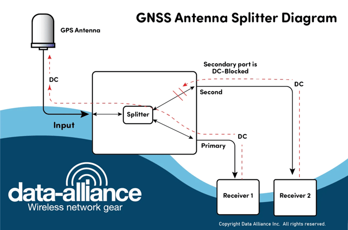
The GNSS splitter is highly isolated to minimize the risk of unwanted interference or interaction between different GNSS receivers. Port-to-port isolation mitigates oscillation problems like local oscillator leakage and reduced yields.
Insertion losses are another factor that has to be considered when using a GNSS splitter. Basic 1x2 GNSS splitters that send half of the input signal to each output port have signal losses of approximately -3 dB, while a 1x3 splitter has an insertion loss of -5 dB and a 1x4 splitter has an insertion loss of -7 dB. This means that the splitter with the fewest ports should be selected, to keep insertion losses to a minimum. Good build quality is essential for this component as GNSS splitters and the attached antenna are vulnerable to becoming a point of failure for all connected receivers. GNSS splitters that are four ways or higher will affect a larger number of receiving devices if there is a failure or downtime.
Most designs are built to withstand indoor and outdoor conditions with suitable ingress protection ratings. The cost of a quality splitter may be greater than the cost of basic GNSS antennas and cables for each receiver.
Key Benefits
Using a GNSS splitter provides several advantages:
- Reduces the need for multiple antennas and cable runs
- Lowers installation cost and time
- Enables synchronized timing across multiple receivers
- Supports centralized antenna deployment in constrained environments
This is especially valuable in telecom, IoT, and infrastructure applications where antenna placement is limited.
Critical Performance Factors
1. Insertion Loss
Signal loss increases with the number of output ports:
- 1x2: ~3 dB
- 1x4: ~7 dB
- 1x8: ~10–11 dB
Best practice: Use the smallest splitter that meets your system requirements to minimize loss.
2. Isolation
High port-to-port isolation prevents interference between receivers.
- Typical: >18–25 dB isolation
- Prevents:
- Local oscillator leakage
- Receiver interaction
- Signal degradation
3. Impedance Matching
- Standard: 50 Ohms
Ensures compatibility with RF cables, antennas, and GNSS receivers
Types of GNSS Splitters
Passive GNSS Splitters (DC Pass)
Passive splitters:
- Do not require an external power supply
- Pass DC power from the receiver to the antenna
- Are simple, reliable, and cost-effective
Powering methods:
- Single receiver (DC pass on one port)
- Dual receiver redundancy
- DC over coax (bias-T configurations)
Active GNSS Splitters (Powered)
Active splitters include an internal power supply:
- Provide controlled DC voltage to the antenna
- Improve system stability in multi-receiver setups
- Typical voltage range: 2.5V to 12V DC
These are preferred in professional and mission-critical deployments.
Amplified GNSS Splitters
Amplified splitters include built-in gain to offset losses:
- Compensate for splitter + cable loss
- Typical gain: 10–24 dB
- Ideal for:
- Long cable runs
- High port-count systems
- Weak signal environments
Rackmount GNSS Splitters
Designed for lab, telecom, and data center environments:
- High port density (up to 32+ outputs)
- Integrated amplification
- Front-panel RF connectors (SMA, BNC, TNC, Type N)
Reliable power supplies for continuous operation
Mechanical & RF Design Considerations
Typical Data Alliance–style specifications include:
RF Connectors
Construction
- Rugged aluminum housing
- EMI shielding
- Weatherproofing (for outdoor models)
- Mounting flanges or brackets
Protection Features
- Surge protection
- ESD protection
- Sealed enclosures (IP-rated options)
Electrical Specifications (Typical)
- Frequency range: 1–2 GHz
- Impedance: 50 Ohm
- Insertion loss: <3–10 dB (depending on ports)
- Isolation: >18 dB
- Gain (amplified): up to 24 dB
- Noise figure: ~1.5–2 dB
- DC pass: 3–12 VDC
Applications
Splitters are used in precision GNSS navigation and testing applications that require highly accurate GNSS time, and location data. They are especially useful in devices or vehicles that can only accommodate a single GNSS antenna.
Precision GNSS & Timing Systems
- Surveying and mapping
- Reference stations
- Telecom synchronization
- Timing systems (NTP/PTP servers)
Important: Some timing systems require a load simulation (resistor) to emulate an antenna for proper operation.
GNSS splitters are routinely used with NTP servers Network Time Protocol (NTP) servers are responsible for synchronizing the clocks of networked computers and other devices. The NTP server receives a GNSS signal via a splitter to use the satellite broadcast signal as a primary time source. These open-circuit devices have over current antenna detection. An attached GNSS splitter must emulate an antenna for the NTP to function. This is done by fitting a resistor across the outputs of a GNSS splitter. .
Telecommunications Infrastructure
- Cellular base stations
- 5G synchronization networks
Distributed timing systems
UAVs, Robotics, and IoT
- Drones and autonomous vehicles
- Robotics navigation
- Low SWaP (Size, Weight, and Power) systems
Splitters reduce antenna count while maintaining high precision.
Best Practices for Deployment
- Use low-loss coaxial cable (LMR-series or equivalent)
- Minimize cable length where possible
- Select high-quality connectors (SMA, Type N)
- Ensure proper grounding and surge protection
- Match splitter type (passive vs active) to system power design
Conclusion
GNSS splitters provide a cost-effective and reliable method to distribute a single antenna signal across multiple receivers. When properly selected and installed, they maintain signal integrity while simplifying system architecture.
Key takeaways:
- Choose the lowest port count needed to minimize loss
- Use active or amplified splitters for larger systems
- Ensure proper powering and isolation
- Prioritize build quality and RF performance
Quick Summary
- A GNSS splitter divides one antenna signal into multiple outputs
- Signal quality is preserved, with only insertion loss as a tradeoff
- Passive splitters draw power from receivers
- Active splitters use an external power supply
Amplified splitters compensate for signal loss in complex systems
FAQs
How many receivers can be connected to a single GNSS antenna using a splitter?
The number of receivers depends on the splitter type. Common configurations include 1x2, 1x4, 1x8, and even high-capacity options such as 1x32 or 1x64 for large synchronization or laboratory systems.
Does using a GNSS splitter weaken the GNSS signal?
Yes, all splitters introduce insertion loss. A basic 1x2 splitter typically loses around –3 dB per output, while splitters with more ports have higher losses. Amplified splitters compensate for this by boosting the signal.
What does port-to-port isolation mean in a GNSS splitter?
Port-to-port isolation prevents interference between connected receivers. Good isolation avoids issues like local oscillator leakage or unstable receiver performance.
Can a single splitter support multiple GNSS constellations?
Yes. Most GNSS splitters support GPS, GLONASS, Galileo, and other GNSS signals, typically covering the L1, L2, and L5 frequency bands.
When should I choose an active GNSS splitter instead of a passive one?
Choose an active splitter when you need internal amplification or when the antenna requires stable, dedicated power. Passive splitters are suitable when connected receivers already provide adequate DC power.
Are GNSS splitters suitable for outdoor installations?
Many GNSS splitters are designed with weather-resistant housings, EMI shielding, surge protection, and ingress protection ratings, making them suitable for both indoor and outdoor use.