


Antennas, Antenna Cables, Wireless Products: Technical Articles
Antenna Cables: Crimped vs. Soldered RF Connectors
Table of Contents
- Crimp and soldered termination methods for RF connectors
- Connector Types: Crimp vs. Solder
- Common Configurations by Connector Type
- Mixed-Method: Crimp + Solder
- Section Summary
- Signal Loss: Soldered vs. Crimped Connectors
- Key Takeaways
- Where Soldering Might Be Better
- Recommendation
- Best Choice for Quality: Crimp + Solder Hybrid (if possible)
- Fully Crimped Connectors – Still a Strong Option
- Fully Soldered Connectors – High Skill Requirement
- Speed Comparison
- In summary
- FAQs
Crimp and soldered termination methods for RF connectors
These are two distinct types of termination methods used for RF antenna cable connectors like RP-SMA, SMA, and N-Type. Each has its own construction, tooling requirements, and application strengths.
Connector Types: Crimp vs. Solder
| Feature | Crimp Connector | Solder Connector |
|---|---|---|
| Assembly Method | Uses a crimping tool to compress the connector ferrule onto the cable | Requires a soldering iron to melt solder for attachment |
| Typical Parts | Crimp pin (center), crimp ferrule (outer shield) | Soldered center pin and/or shield |
| Repeatability | High – often used in production environments | Lower – requires more precision and experience |
| Tool Required | Dedicated crimping tool for specific connector size | Soldering iron and sometimes a jig |
| RF Performance | Very good, especially with proper tooling | Excellent when done properly, especially at high frequencies |
| Field Assembly | Easier, faster – preferred for on-site work | More time-consuming, usually for custom or lab builds |
| Reliability | Mechanically strong and vibration-resistant | Thermally bonded – strong but may degrade if solder is poor |
Common Configurations by Connector Type
● SMA / RP-SMA
Crimp versions are most common for standard coaxial cables like RG174, RG58, LMR-200, etc.
Soldered versions are used in applications where precision, signal integrity, or high frequency is critical.
● N-Type
Often available in both crimp and solder types.
Crimp is favored in telecom and outdoor RF setups due to its rugged mechanical retention.
Solder N-Type connectors may be used in lab/test environments.
Mixed-Method: Crimp + Solder
Some connectors use a hybrid method, where:
The center conductor is soldered to the pin,
The outer shield is crimped to the ferrule.
This combines the electrical precision of solder with the mechanical strength of a crimp.
Section Summary
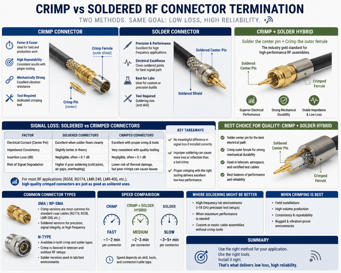
Crimp and soldered connectors are different types of RF terminations. Crimp connectors are generally faster to install and more consistent for field and production work, while soldered connectors may offer slightly better performance in precision or high-frequency applications—when done correctly.
Signal Loss: Soldered vs. Crimped Connectors
| Factor | Soldered Connectors | Crimped Connectors |
|---|---|---|
| Electrical Contact (Center Pin) | Can create an excellent electrical connection when solder flows cleanly | Also excellent when properly crimped with the right die size and pressure |
| Impedance Consistency | Slightly better in theory if precision soldering preserves geometry | Very consistent with high-quality tooling and connectors |
| Insertion Loss (dB) | Negligible, often < 0.1 dB difference compared to crimp | Negligible, often < 0.1 dB difference compared to solder |
| Risk of Signal Degradation | Higher if soldering introduces air gaps, cold joints, or overheats dielectric | Lower risk of thermal damage, but poor crimps can cause loose or high-resistance contacts |
Key Takeaways
There is no meaningful difference in signal loss if both connectors are installed correctly.
Improper soldering (e.g., cold joints, excess solder, overheating) can actually introduce more signal loss or reflection than a properly crimped connector.
Crimping, when done with the correct tool and die set for the cable type, provides excellent low-loss performance and is often the preferred method in production and field environments.
Where Soldering Might Be Better
In high-frequency lab environments (e.g., >18 GHz precision test setups), hand-soldered connectors by trained technicians may offer slightly better return loss or VSWR.
For custom or exotic cable assemblies where crimp tools aren’t available or practical.
Recommendation
For most commercial RF uses—including coax like RG58, RG174, LMR-240, LMR-400, etc.—high-quality crimped connectors are just as good as soldered ones in terms of signal loss. Focus on:
Using brand-matched crimp connectors and tools.
Verifying center pin alignment and shield contact.
Testing completed cables with a network analyzer or TDR if critical.
Best Choice for Quality: Crimp + Solder Hybrid (if possible)
For the highest quality and consistency, the industry gold standard—especially in high-performance RF—is:
Solder the center pin + Crimp the outer ferrule
This method offers:
Superior electrical performance (clean soldered signal path)
Strong mechanical durability from the crimped shield/ferrule
Stable impedance and low loss, which is critical in RF assemblies
This hybrid approach is widely used in telecom, aerospace, and certified test cables because it combines the electrical advantages of soldering with the mechanical reliability and speed of crimping.
Fully Crimped Connectors – Still a Strong Option
If production speed and consistency are more critical (e.g., for high-volume reworking), and you’re using high-quality components and calibrated crimp tools:
Fully crimped connectors (center + ferrule) can still meet excellent performance thresholds—if done right.
However:
The center pin crimp must be perfect—any variation in cable strip length or crimp die can introduce VSWR and signal degradation.
Crimping requires precise tools matched to each cable/connector size.
Fully Soldered Connectors – High Skill Requirement
While soldering both the center and the outer conductor is technically fine:
It’s slower and more prone to error (e.g., cold joints, melted dielectric, inconsistent solder fill).
If your team is not extremely experienced, it could reduce overall quality.
Fully soldered assemblies are often best left to prototyping or lab environments, not production reworking.
Speed Comparison
| Method | Relative Speed | Notes |
|---|---|---|
| Fully Crimped | Fastest | Ideal for production with consistent quality using correct tooling |
| Crimp + Solder | Medium | Slightly slower but best quality; requires soldering station for center pin |
| Fully Soldered | Slowest | High risk of variability; requires training and quality inspection |
In summary
Both crimped and soldered RF connector terminations can deliver excellent performance when executed correctly, with virtually no meaningful difference in signal loss. The real distinction lies in consistency, ease of installation, and application context. Crimp connectors stand out for their speed, repeatability, and reliability in field and production environments, while soldered connectors can offer slight advantages in precision applications—provided they are handled by skilled technicians. For those seeking the best of both worlds, the hybrid approach of soldering the center pin and crimping the outer ferrule provides an optimal balance of electrical performance and mechanical strength. Ultimately, the key to quality isn’t the method itself, but the proper use of tools, technique, and attention to detail during assembly.
FAQs
What is the main difference between crimp and solder termination methods for RF connectors?
Crimp termination uses a crimping tool to compress the ferrule and secure the connector to the cable, while solder termination requires melting solder with a soldering iron to bond the conductor and/or shield.
Which connector types are commonly available in crimp and solder versions?
- SMA / RP-SMA: Crimp versions are most common for cables like RG174, RG58, and LMR-200, while soldered versions are preferred in precision or high-frequency applications.
- N-Type: Available in both crimp and solder types. Crimp is favored in telecom and outdoor RF, while solder is used more in lab/test environments.
Which method is better for field assembly?
Crimp connectors are generally better for field use because they are faster, easier, and more repeatable. Soldering takes more time and precision, making it better suited for custom or lab environments.
Do crimped and soldered connectors perform differently in terms of signal loss?
When properly assembled, both methods offer nearly identical performance, with insertion loss differences of less than 0.1 dB. Poor technique, however, can introduce issues: bad solder joints may create reflections or added loss, while a poor crimp may result in loose or high-resistance connections.
What tools are required for each termination method?
- Crimp connectors: Require a calibrated crimping tool matched to the cable and connector type.
- Solder connectors: Require a soldering iron (and sometimes a jig) plus soldering skills.
Which method is more reliable for high-frequency or precision RF work?
Soldering can offer slightly better impedance consistency and return loss in precision lab setups (e.g., >18 GHz). However, crimping with high-quality connectors and tools is usually sufficient for most commercial RF work.
What is the advantage of the hybrid crimp + solder method?
The hybrid approach solders the center conductor to ensure electrical precision, while crimping the outer shield provides mechanical strength. This method combines the best of both worlds—excellent signal integrity and strong durability—and is often used in telecom, aerospace, and certified test cables.
Which termination method is best for production environments?
Fully crimped connectors are the fastest and most consistent choice for production and field rework, provided the correct tooling is used. The hybrid crimp + solder method delivers the highest quality but is slower. Fully soldered assemblies require high skill and are generally best reserved for prototyping or specialized lab work.