Antennas, Antenna Cables, Wireless Products: Technical Articles
UHF Connectors: Specifications and Applications
Table of Contents
UHF Connectors:
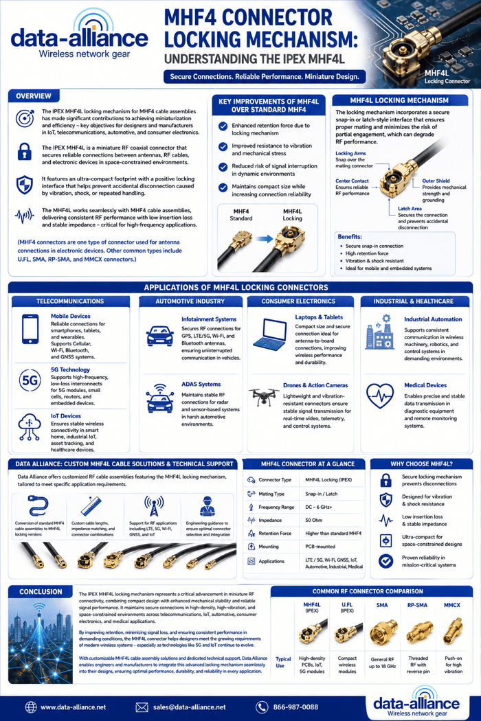
The Ultra High-Frequency (UHF) connector is a threaded coaxial connector that was developed in the 1930s by engineers at Amphenol. They named these connectors at a time when the UHF frequency range was considered to be 300 MHz and upward. Despite their name, contemporary UHF connectors are primarily used for lower-frequency applications rather than true modern UHF bands.
UHF connectors were initially used in radio broadcasting and early RF systems, with a design that is mechanically related to banana plugs. Over time, they became one of the most widely used RF connectors in legacy communication systems due to their durability, simplicity, and low cost.
Today, UHF connectors remain common in many practical installations, especially in ham radio, CB radio, and marine communication systems. Within the Data Alliance ecosystem, UHF connectors are often found in legacy antenna systems, cable assemblies, and field-deployable RF setups where ruggedness is more important than precision impedance matching.
Physical Specifications of the UHF Connector
The UHF connector consists of individual male and female RF connectors that form a secure mated connection using a threaded coupling mechanism. This screw-on design provides a strong mechanical connection that resists vibration and physical stress, making it suitable for mobile and outdoor installations.
UHF connectors do not follow a tightly controlled impedance standard. However, most manufacturers design them to be inter-compatible across a range of coaxial cable types such as RG58, RG8, and RG213, which are commonly used in RF and antenna applications.
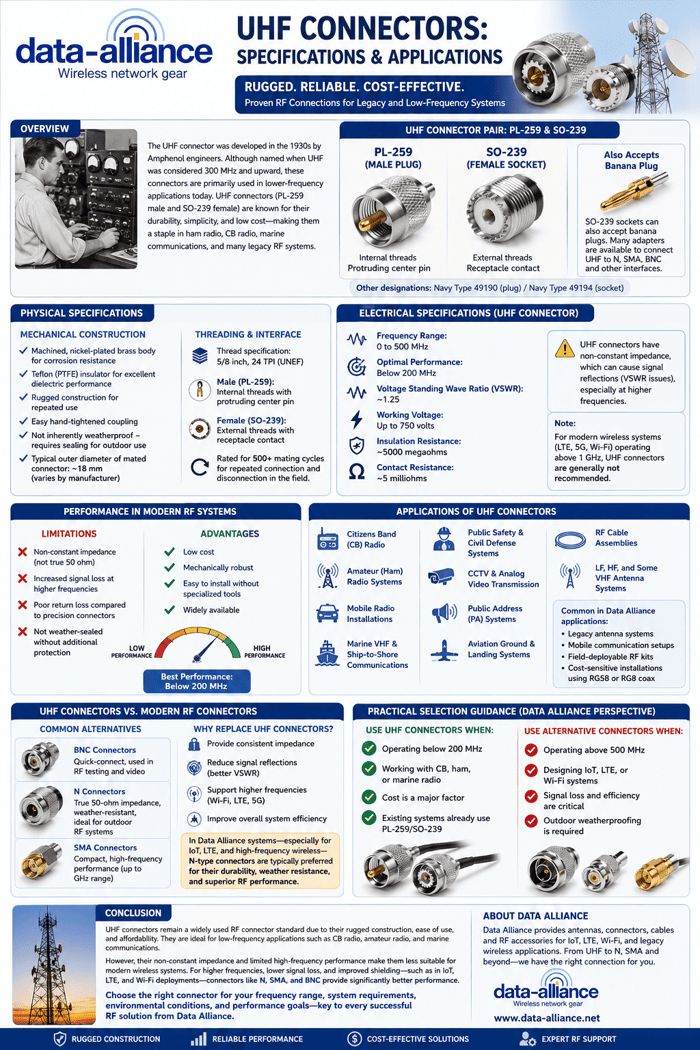
PL-259 and SO-239
These Signal Corps nomenclatures refer to the most common UHF connector pair:
- PL-259: Male plug
- SO-239: Female socket
The SO-239 socket can also accept a banana plug, and a wide variety of inter-series UHF adapters are available to connect UHF interfaces to other connector types such as N, SMA, or BNC.
Alternative military designations include:
- Navy type 49190 (plug)
- Navy type 49194 (socket)
Although these terms have largely fallen out of modern use, PL-259 and SO-239 remain industry-standard terminology.
Mechanical Construction
The UHF connector’s body is typically made from machined, nickel-plated brass, providing corrosion resistance and mechanical durability. It uses a Teflon (PTFE) insulator, which offers good dielectric properties and thermal stability.
Key physical features include:
- Rugged construction for repeated use
- Easy hand-tightened coupling
- Not inherently weatherproof (requires sealing for outdoor use)
- Typical outer diameter of mated connector: ~18 mm (varies by manufacturer)
Threading and Interface
- Thread specification: 5/8 inch, 24 TPI (UNEF)
- Male connector: Internal threads with a protruding center pin
- Female connector: External threads with a receptacle contact
UHF connectors are generally rated for 500+ mating cycles, making them suitable for repeated connection and disconnection in field environments.
Electrical specifications of the UHF connector
One of the defining characteristics of UHF connectors is their non-constant impedance, which distinguishes them from precision RF connectors such as SMA, N, or TNC.
This impedance inconsistency can introduce signal reflections (VSWR issues), especially at higher frequencies. As a result, UHF connectors are best suited for lower-frequency RF applications.
Typical Electrical Characteristics:
- Frequency range: 0 to 500 MHz
- Optimal performance: Below 200 MHz
- Voltage Standing Wave Ratio (VSWR): ~1.25
- Working voltage: Up to 750 volts
- Insulation resistance: ~5000 megaohms
- Contact resistance: ~5 milliohms
Because of their design, UHF connectors may experience impedance discontinuities, especially in the female (SO-239) interface. This can lead to signal reflections and reduced efficiency in higher-frequency systems.
For modern wireless applications such as LTE, 5G, and Wi-Fi, where frequencies exceed 1 GHz, UHF connectors are generally not recommended.
Performance Considerations in Modern RF Systems
In today’s RF environment—especially in IoT, cellular, and high-frequency wireless systems—connector performance plays a critical role in overall signal integrity.
Limitations of UHF Connectors:
- Non-constant impedance (not true 50 ohm across interface)
- Increased signal loss at higher frequencies
- Poor return loss compared to precision connectors
- Not weather-sealed without additional protection
Advantages:
- Low cost
- Mechanically robust
- Easy to install without specialized tools
- Widely available
Because of these trade-offs, UHF connectors are often used in applications where:
- Frequency is relatively low
- Cable runs are short to moderate
- Cost is a primary consideration
Absolute RF performance is not critical
Applications of UHF connectors
UHF connectors are a cost-effective, robust RF connector solution for general-purpose use. They perform best at frequencies below 200 MHz and are widely used in both commercial and hobbyist applications.
Common Applications:
- Citizens Band (CB) radio communications
- Amateur (ham) radio systems
- Mobile radio installations
- Marine VHF and ship-to-shore communications
- Public safety and civil defense systems
- CCTV and analog video transmission
- Public address (PA) systems
- Aviation ground and landing systems
- RF cable assemblies
- LF, HF, and some VHF antenna systems
Within Data Alliance product applications, UHF connectors are commonly found in:
- Legacy antenna systems
- Mobile communication setups
- Field-deployable RF kits
Cost-sensitive installations using RG58 or RG8 coax
UHF Connectors vs. Modern RF Connectors
As RF systems have evolved, newer connector types have largely replaced UHF connectors in high-performance applications.
Common Alternatives:
- BNC connectors: Quick-connect, used in RF testing and video
- N connectors: True 50-ohm impedance, weather-resistant, ideal for outdoor RF systems
- SMA connectors: Compact, high-frequency performance (up to GHz range)
Why Replace UHF Connectors?
Users often replace UHF connectors with BNC or N connectors using inter-series adapters because:
- They provide consistent impedance
- They reduce signal reflections (better VSWR)
- They support higher frequencies (Wi-Fi, LTE, 5G)
- They improve overall system efficiency
In Data Alliance antenna systems—especially for IoT, LTE, and high-frequency wireless—N-type connectors are typically preferred for their durability, weather resistance, and superior RF performance.
Practical Selection Guidance (Data Alliance Perspective)
When selecting RF connectors for antenna systems:
Use UHF connectors when:
- Operating below 200 MHz
- Working with CB, ham, or marine radio
- Cost is a major factor
- Existing systems already use PL-259/SO-239
Use alternative connectors when:
- Operating above 500 MHz
- Designing IoT, LTE, or Wi-Fi systems
- Signal loss and efficiency are critical
- Outdoor weatherproofing is required
Conclusion
UHF connectors remain a widely used RF connector standard due to their rugged construction, ease of use, and affordability. Originally designed for early radio systems, they continue to serve reliably in low-frequency applications such as CB radio, amateur radio, and marine communications.
However, their non-constant impedance and limited high-frequency performance make them less suitable for modern wireless systems. For applications requiring higher frequencies, lower signal loss, and improved shielding—such as IoT, LTE, and Wi-Fi deployments—connectors like N, SMA, and BNC provide significantly better performance.
Ultimately, the choice of connector should be based on frequency range, system requirements, environmental conditions, and overall performance goals—key considerations in all Data Alliance RF and antenna solutions.
FAQs
What is a UHF connector used for?
UHF connectors are used in low-frequency RF applications such as CB radio, ham radio, marine VHF, and general-purpose antenna connections. They are valued for durability and ease of installation but are best suited for frequencies below 200 MHz.
What is the difference between PL-259 and SO-239?
PL-259 is the male UHF connector (plug), while SO-239 is the female connector (socket). They are designed to mate together using threaded coupling and are the most common UHF connector pair.
What frequency range do UHF connectors support?
UHF connectors typically operate from DC up to 500 MHz, but they perform best below 200 MHz. At higher frequencies, signal loss and impedance mismatch become significant.
Why are UHF connectors not ideal for modern wireless systems?
UHF connectors have non-constant impedance, which can cause signal reflections (VSWR issues) and increased loss at higher frequencies. This makes them unsuitable for LTE, 5G, and Wi-Fi applications above 1 GHz.
Are UHF connectors weatherproof?
No, UHF connectors are not inherently weatherproof. For outdoor use, they require additional sealing such as weatherproof tape or coax seal to prevent moisture intrusion and signal degradation.
What are the main advantages of UHF connectors?
UHF connectors are low cost, mechanically robust, easy to install, and widely available. They are ideal for legacy systems and applications where high-frequency performance is not critical.
What connectors are better alternatives to UHF?
For higher-frequency and modern RF systems, connectors like N-type, SMA, and BNC are preferred. They provide consistent impedance, lower signal loss, and better performance for IoT, LTE, and Wi-Fi applications.