


Antennas, Antenna Cables, Wireless Products: Technical Articles
RG58 Compared to LMR-200 & LMR-100 Coax: Shielding & Signal Loss
Table of Contents
RG58 Coaxial Cable Specifications
Comparison Between RG58, LMR-100, and LMR-200 Coaxial Cables
RG58 coaxial cable is one of the most widely used 50-ohm RF coaxial cables, especially in legacy, test, and low-power wireless applications. Despite the availability of newer low-loss coaxial cables, RG58 remains popular due to its flexibility, durability, and long-standing military specification heritage. To better understand where RG58 fits in modern RF systems, it is helpful to compare it with newer alternatives such as LMR-100 and LMR-200.
This article provides a detailed comparison of RG58, LMR-100, and LMR-200, covering construction, electrical performance, attenuation characteristics, and typical applications.

Shared Characteristics of RG58, LMR-100, and LMR-200
RG58, LMR-100, and LMR-200 share several core characteristics that make them suitable for RF and antenna cable applications:
- 50-ohm nominal impedance, ideal for RF, data, and wireless communications
- Polyethylene (PE) dielectric, offering good electrical insulation and environmental resilience
- PVC outer jacket, providing flexibility and basic protection against abrasion and weather
Despite these similarities, their internal construction, shielding effectiveness, conductor size, and signal loss differ significantly, which impacts performance across different frequencies and cable lengths.
Structural comparison of RG58 and LMR-100
LMR-100 is a miniature low-loss coaxial cable designed to provide improved shielding and electrical performance compared to RG58 while maintaining a smaller overall diameter.
Key Structural Characteristics of LMR-100:
- Nominal impedance: 50 Ohms
- Overall diameter: 2.79 mm (0.110 inches)
- Center conductor: 0.46 mm solid bare copper-covered steel (BCCS)
- Shielding: Double-shielded, consisting of:
- Aluminum foil tape (inner shield)
- Tinned copper braid (outer shield)
Differences Between RG58 and LMR-100:
- RG58 typically uses a stranded copper center conductor, while LMR-100 uses solid BCCS
- LMR-100’s double shielding provides better EMI and RFI rejection
- RG58 is larger and more flexible, while LMR-100 prioritizes compact size and improved shielding
LMR-100 is commonly used where space constraints are critical but performance beyond RG58 is still desired.
Structural Comparison: RG58 vs. LMR-200
LMR-200 is a low-loss coaxial cable engineered for improved performance over longer cable runs and higher frequencies.
Key Structural Characteristics of LMR-200:
- Overall diameter: 6.1 mm (0.24 inches)
- Center conductor diameter: 1.42 mm
- Conductor material: Bare copper (BC)
- Shielding: Double-shielded, consisting of:
- Aluminum foil tape
- Tinned copper braid
The larger conductor and enhanced shielding significantly reduce signal attenuation and improve noise rejection compared to RG58.
Attenuation Comparison (dB per Foot)
Attenuation, or signal loss, is one of the most critical factors when selecting a coaxial cable for RF and antenna applications.
Frequency (MHZ) | RG58 | LMR-200 |
100 | 0.048 | 0.038 |
200 | 0.073 | 0.048 |
400 | 0.114 | 0.068 |
500 | 0.125 | 0.070 |
900 | 0.195 | 0.228 |
1000 | 0.213 | 0.119 |
1500 | 0.245 | 0.129 |
2400 | 0.354 | 0.169 |
As frequency increases, attenuation rises significantly for RG58. This makes RG58 less suitable for long cable runs at higher frequencies, especially above 1 GHz, where low-loss coaxial cables provide clear advantages.
About RG58
Electrical Characteristics of RG58
RG58 is designed to meet established U.S. military standards and provides predictable electrical performance.
Typical Electrical Specifications:
- Nominal impedance: 50 Ohms ±2 Ohms
- Frequency range: DC to 5 GHz
- Conductor resistance: 38.4 Ohms
- Dielectric resistance: 500 Ohms
These characteristics make RG58 suitable for short-distance, low-power RF applications where flexibility and cost are priorities.
Structure and material composition of RG58 cable
Like all other coaxial cables, RG58 comprises an inner conducting wire surrounded by an insulating layer and outer conducting shielding. It is typically manufactured to the U.S. specifications MIL-C-17F and MIL-C-17G 9.
- The conductor has a diameter of 0.91mm (0.036 inches) and is made from stranded (7 or 19 strand tinned copper wire, which has added resistance to oxidation and is readily soldered. Solid conductor variants are also available.
- The dielectric diameter is 2.95mm (0.116 inches), made from solid polyethylene (PE). Polythene is heat stable up to a maximum operating temperature of 80 degrees Celsius (176 degrees Fahrenheit) and provides flexibility, fire resistance, resilience against abrasions, and weatherproofing.
- RG58 is shielded with flexible and heat-stable tinned copper wire braid, with coverage between 70% and 95%, depending on the manufacturer.
- The outer jacket of the RG58 cable is made from UV-resistant PVC, which is heat-stable but has limited resistance to acids, alkalis, and inorganic solvents.
- The overall diameter of this cable is 5mm (0.2 inches).
Meaning of the RG Designation
RG stands for “Radio Guide” or “Radio Frequency Government”, a designation originating from U.S. military standards developed in the 1960s. RG cables were specified under MIL-C-17 standards to ensure compatibility and reliability in military and commercial RF systems.
The number following “RG” refers to a specific construction standard, not the physical gauge of the cable. Some cables include a “/U” suffix, indicating universal construction.
It is important to note that RG is not a proprietary or manufacturer-controlled standard. As a result, construction details can vary slightly between manufacturers, making it essential to verify specifications before selecting a cable.
RG58 Applications
RG58 is best suited for short cable runs and low-power RF applications, including:
- RF testing and measurement setups
- Amateur (ham) radio and emergency services
- Marine VHF radio systems
- WLAN and Wi-Fi antennas
- Laboratory and bench-top RF connections
Due to its relatively high attenuation, RG58 is generally not recommended for long antenna cable runs in modern wireless systems.
RG vs. Low-Loss Coaxial Cables
In general:
- 75-ohm coaxial cables are used for audio and video applications
- 50-ohm coaxial cables are used for RF, data, and wireless communications
While RG58 is a 50-ohm cable, it exhibits higher attenuation than modern low-loss coaxial cables. For wireless applications requiring longer cable lengths, low-loss coaxial cables such as LMR-100, LMR-200, and larger LMR-series cables are preferred.
RG standard of Coaxial Cable
RG is a robust coaxial technology standard - one of the original standards for coaxial cable technology, created for the US military in the 1960's. RG is not a specific manufacturer's standard: All coax manufacturers can use RG and a standard by using the letters RG ("Radio Guide") followed by a number corresponding to a certain standard with a particular set of specifications. Sometimes, the letter "/U" follows the number for the "Universal" standard (i.e., the cable construction is intended for universal applications).
There is no standardization among manufacturers to ensure that every aspect of the cable is constant, so it helps to know the specifications of the cable you need.
RG technology is used in military and commercial applications in various environments.
Generally, 75 Ohm cables are used in audio/video applications, and 50 Ohm cables are used in data applications. The 50 Ohm RG cables typically lose too much signal through attenuation to be appropriate for wireless applications unless the cable is short. Low-loss coax is the only viable solution for antenna cables of longer lengths.
Conclusion
RG58 remains a widely used 50-ohm coaxial cable thanks to its durability, flexibility, and long-standing MIL-spec heritage. However, when lower signal loss and improved shielding are required—especially for longer cable runs—modern low-loss options such as LMR-100 and LMR-200 provide clear performance advantages. While RG58 is well-suited for general RF, testing, and low-power communication applications, selecting the appropriate coax type ultimately depends on the desired attenuation levels, operating frequency, and installation environment.
FAQs
What is the main difference between RG58 and low-loss options like LMR-100 and LMR-200?
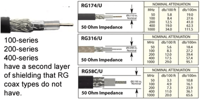
RG58 uses a single braided shield and has higher signal loss, while LMR-100 and LMR-200 use double shielding (aluminum tape + braided copper) for reduced attenuation. LMR-200 also has a larger conductor and thicker diameter, resulting in significantly lower loss over longer distances.
What is the operating impedance and frequency range of RG58?
RG58 has a nominal 50-ohm impedance and supports frequencies up to 5 GHz, making it suitable for many RF, testing, and communication applications.RG58 has a nominal 50-ohm impedance and supports frequencies up to 5 GHz, making it suitable for many RF, testing, and communication applications.
What materials are used in the construction of RG58 cable?
RG58 consists of a stranded tinned-copper conductor, solid polyethylene (PE) dielectric, a tinned-copper braided shield, and a UV-resistant PVC outer jacket. This design provides flexibility, weather resistance, and reliable RF performance.
What applications is RG58 suitable for?
RG58 is commonly used in ham radio, testing and measurement, marine VHF, WLAN antennas, and low-power RF communication systems. It performs best in short cable runs due to its higher attenuation compared to low-loss coax.
Why is RG58 not ideal for long antenna cable runs?
Its attenuation increases significantly with frequency, meaning longer runs can result in substantial signal loss. For extended distances or higher-frequency applications, low-loss coaxial cables like LMR-200 or LMR-400 are recommended.