


Antennas, Antenna Cables, Wireless Products: Technical Articles
Fresnel Zone: Key for Long Range WiFi Links
Table of Contents
- Visual Line of Sight – Data Alliance
- Fresnel Zone
- Why the Fresnel Zone Matters in Long-Range Links
- Backhaul Example: Fresnel Zone with Obstruction
- Reflection, Diffraction, and Signal Behavior
- Fresnel Zone as an Electromagnetic Phenomenon
- Fresnel Zone Structure
- Correct vs Incorrect Antenna Placement
- Directional vs Omni Antennas and Fresnel Effects
- Ground Clearance and Installation Best Practices
- Practical Data Alliance Applications
- In Summary
- FAQs
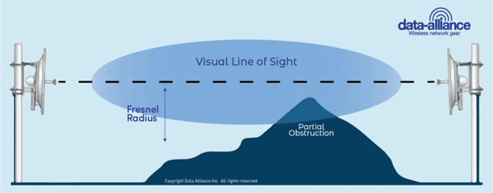
Visual Line of Sight – Data Alliance
Fresnel Zone
The wireless or Wi-Fi signal does not travel in a perfectly straight line like a laser. Instead, it propagates in a shape similar to an elliptical or football-shaped pattern between the transmitting and receiving antennas. The Fresnel Zone represents this three-dimensional area around the direct line-of-sight path.
More specifically, the Fresnel zone is the elliptical region between a transmitter and receiver where radio waves spread and interact. The radius of the Fresnel zone depends on:
- The distance between the transmitter and receiver
- The frequency of the RF signal
Lower frequencies (such as 900 MHz) produce larger Fresnel zones, while higher frequencies (such as 5 GHz or 6 GHz WiFi) produce smaller Fresnel zones.
In practical Data Alliance applications—such as long-range WiFi links, point-to-point bridges, and backhaul systems—understanding and maintaining Fresnel zone clearance is critical for achieving maximum performance.
Why the Fresnel Zone Matters in Long-Range Links
The Fresnel zone becomes especially important in long-distance point-to-point wireless links, including:
- Building-to-building WiFi bridges
- Rural internet backhaul links
- Surveillance and IoT connectivity between remote sites
Even if you have a clear visual line of sight (LOS), your link can still perform poorly if the Fresnel zone is obstructed.
This is a key point often addressed in Data Alliance technical support:
Line of sight alone is not enough — Fresnel clearance is required for optimal throughput.
Backhaul Example: Fresnel Zone with Obstruction
Radio transmissions can either reach the receiver directly through a clear line of sight, making the strongest reception. Or can be reflected from spatial objects such as buildings and land feature either vertically or horizontally and assume a defected path. Reflected waves, depending on the angle of reflection travel further to reach the receiver and arrive phase-shifted at the antenna.
Fresnel Zone is an electromagnetic phenomenon, in which light waves or radio signals get diffracted or bent from solid objects near their path. The radio waves reflecting off the objects may arrive out of phase with the signals that traveled directly to the receiving antenna thus reducing the power of the received signal. Therefore you have to have more than visual line-of-sight: You need for the Fresnel zone to be clear or the obstructions will block part of your throughput - you will have lower rate of through-put if there is an obstruction in this zone.
The Fresnel zone is made up of three main zones. The first zone is closest to the line of sight and is the strongest. The second zone is between the first and the weakest third zone. Ideally, the first zone should be at least 60% free of abstraction for effective transmission.
Below are examples of the correct and incorrect placement of the antennas/radios on the towers:

Receiver’s antenna receives and combines both the reflected radio waves and the main wave. This can lead to constructive or destructive interference depending on the phase shift angle difference. If the two signals are phase-shifted by 180 degrees, the signals cancel out. Measurements of the Fresnel zone can be used to determine the expected phase shifts at the receiver.
Directional antennas are especially susceptible to the Fresnel zone effects. If destructive interference occurs in the forward direction of the antenna little or no reception will occur. With omni-directional antennas, the antenna will still radiate in different directions and pick up fair reception if destructive interference occurs in only one direction.
Ground clearing the Fresnel zone effectively improve the transmission throughput. With the rule of thumb, the acceptable obstacle clearance ratio is 60%.
Reflection, Diffraction, and Signal Behavior
Radio transmissions can reach the receiver in multiple ways:
1. Direct Path (Line of Sight)
- Strongest and most desired signal
- Travels straight between antennas
2. Reflected Paths
- Bounce off buildings, ground, water, or terrain
- Arrive at different times and phases
3. Diffracted Paths
- Bend around obstacles near the signal path
- Occur within the Fresnel zone
The Fresnel zone is where these interactions happen.
Fresnel Zone as an Electromagnetic Phenomenon
The Fresnel zone represents an electromagnetic field region where radio waves:
- Spread outward
- Reflect off nearby objects
- Interfere with each other
When reflected signals combine with the direct signal, two outcomes are possible:
Constructive Interference
- Signals reinforce each other
- Stronger received signal
Destructive Interference
- Signals cancel each other out
- Reduced signal strength or complete signal loss
If signals arrive 180° out of phase, they cancel each other, causing severe degradation.
Why Obstructions Reduce Throughput
When an object enters the Fresnel zone:
- It blocks part of the RF energy
- It causes reflections and phase shifts
- It reduces signal strength and data rate
This results in:
- Lower throughput
- Higher packet loss
- Increased latency
- Unstable connections
From a Data Alliance support perspective, this is one of the most common causes of poor link performance, even when RSSI appears acceptable.
Fresnel Zone Structure
The Fresnel zone is composed of multiple zones:
- First Fresnel Zone (Most Important)
- Second Fresnel Zone
- Third Fresnel Zone
The first Fresnel zone is the most critical because:
- It carries the majority of the signal energy
- It has the greatest impact on signal quality
Rule of Thumb
At least 60% of the first Fresnel zone must be clear of obstructions
This is a widely accepted guideline in RF engineering and is heavily applied in:
- WiFi bridge installations
- LTE/5G antenna deployments
- Outdoor IoT networks
Correct vs Incorrect Antenna Placement
Proper antenna placement directly affects Fresnel zone clearance.
Correct Placement
- Antennas mounted high enough
- Clear path with minimal obstruction
- At least 60% Fresnel clearance
Incorrect Placement
- Antennas too low
- Trees, ground or buildings intruding into the zone
- Partial obstruction causing signal degradation
In Data Alliance deployments, increasing antenna height—even by a few meters—can significantly improve performance by clearing the Fresnel zone.
Directional vs Omni Antennas and Fresnel Effects
Directional Antennas
- Focus energy in a specific direction
- More sensitive to Fresnel zone obstruction
- Higher gain but require precise alignment
If destructive interference occurs in the main beam:
- Signal can drop dramatically
Omni-Directional Antennas
- Radiate in all directions
- Less sensitive to a single obstruction
- Lower gain but more forgiving
However, for long-range links, directional antennas are preferred, provided the Fresnel zone is clear.
Ground Clearance and Installation Best Practices
Clearing the Fresnel zone from the ground is essential.
Best Practices
- Mount antennas higher than surrounding ground or terrain
- Avoid placing antennas behind parapet walls or railings
- Keep the signal path clear of trees and seasonal foliage
- Account for future growth (trees, construction)
60% Clearance Rule
- Minimum acceptable: 60%
- Recommended for high performance: 80%+
Practical Data Alliance Applications
Understanding Fresnel zone clearance is critical for:
1. Long-Range WiFi Bridges
Used in:
- Farms
- Industrial sites
- Rural internet
2. Backhaul Links
Connecting:
- Remote networks
- Surveillance systems
- IoT gateways
3. Antenna Installations
Including:
- High-gain directional antennas
- Yagi, panel, and dish antennas
- Cellular and WiFi antennas
Troubleshooting Fresnel Zone Issues
Common symptoms of Fresnel zone obstruction:
- Good signal strength but low throughput
- Intermittent connectivity
- Performance drops during certain seasons (trees growing leaves)
- High noise or unstable modulation rates
Solutions
- Raise antenna height
- Reposition antennas
- Trim or remove obstacles
- Switch to higher gain directional antennas
- Use shorter link paths if possible
In Summary
The Fresnel zone is a critical factor in RF and WiFi performance:
- Signals travel in an elliptical pattern, not a straight line
- Obstructions in the Fresnel zone reduce performance, even with line of sight
- The first Fresnel zone must be at least 60% clear
- Reflections and diffraction can cause destructive interference
- Proper antenna placement and height are essential
Data Alliance Best Practice
For optimal performance in WiFi, cellular, and IoT deployments:
- Ensure clear Fresnel zone (≥60%)
- Use proper antenna height and alignment
- Select high-quality directional antennas and cables
- Verify installations with real-world testing
A properly cleared Fresnel zone ensures maximum throughput, stability, and reliability, making it a foundational principle in all long-range wireless system designs.
FAQs
What is the Fresnel zone in wireless communication?
The Fresnel zone is the elliptical area between a transmitter and receiver where RF signals travel and spread. It represents the space where radio waves can be affected by obstacles, reflections, and diffraction, impacting signal quality.
Why is the Fresnel zone important for long-range WiFi links?
The Fresnel zone is critical because obstructions within it can reduce signal strength and throughput. Even with clear visual line of sight, blocked Fresnel zones can cause interference and degrade performance in point-to-point wireless links.
What happens if the Fresnel zone is obstructed?
If the Fresnel zone is obstructed by objects like trees, buildings, or terrain, radio waves can reflect or diffract. This can cause destructive interference, reducing signal power, data rates, and overall link reliability.
How much of the Fresnel zone needs to be clear?
As a rule of thumb, at least 60% of the first Fresnel zone should be clear of obstacles to maintain good signal performance. Higher clearance (70–80%) is recommended for optimal results in long-distance links.
What is the difference between line of sight and Fresnel zone clearance?
Line of sight means the antennas can visually see each other, while Fresnel zone clearance ensures the signal path around that line is also free of obstructions. Both are required for strong and stable wireless performance.
How do reflections and phase shifts affect wireless signals?
Reflected signals can arrive at the receiver out of phase with the direct signal. If they are 180° out of phase, they can cancel each other out (destructive interference), leading to weak or unstable connections.
Are directional antennas more affected by Fresnel zone obstruction?
Yes, directional antennas are more sensitive to Fresnel zone obstruction because they focus energy in a specific direction. Any interference in that path can significantly reduce signal strength, unlike omni antennas which receive signals from multiple directions.