15 dBi Directional Yagi Antenna (806–960 MHz)
- SKU:
- A9Y15NfvW
- Availability:
- In stock
- Weight:
- 2.00 LBS
Data Alliance
High-gain 806~960 MHz 15dBi Yagi antenna
Overview
This high-gain 15 dBi Yagi antenna is designed for long-range directional communication in the 900 MHz ISM band, covering applications between 806 MHz and 960 MHz. Its narrow beamwidth and high front-to-back ratio make it ideal for point-to-point RF links, base station access, and cellular signal enhancement, especially in rural or obstructed environments.
|
ELECTRICAL SPECIFICATIONS |
|
|
Frequency Range |
806-960 MHz |
|
Impedance |
50 Ohm |
|
VSWR |
less than 1.5 |
|
Gain |
15 dBi |
|
Polarization |
Horizontal or Vertical |
|
Horizontal 3dB Beam Width |
30° |
|
Vertical 3dB Beam Width |
30° |
|
Front To Back Ratio |
≥18 dB |
|
Lighting Protection |
Direct Ground |
|
Connector |
N-Female |
|
Maximum Power Input-watts |
200 W |
|
MECHANICAL SPECIFICATIONS |
|
|
Length |
1170x172x65mm |
|
Weight |
4.0 lbs |
|
Cable length/Type |
0.5 m SYWV-50-7 |
|
Mounting hardware |
Ø40-Ø60mm |
|
Color |
Black |
|
Elements |
1 Reflector (bottom) 1 Driven element (middle, connected to coax) 16+ Director elements (short elements spaced evenly along the boom) |
|
Boom |
Cylindrical, vertical spine with mounting holes |
|
Weatherproofing |
Outdoor-rated materials, suitable for long-term installation. Weather-resistant powder coating |
Key Features
- High Gain: 15 dBi – provides strong signal focus and long-distance performance.
- Frequency Range: 806–960 MHz – supports:
- GSM-850 / GSM-900
- LoRaWAN
- SCADA / AMR systems
- ISM 902–928 MHz applications
- Polarization: Vertical (default) or horizontal (mounting dependent)
- VSWR: Typically ≤ 1.5:1 for optimal power efficiency
- Impedance: 50 ohms – standard for RF equipment compatibility
- Connector Type: N-Female (stainless steel or nickel-plated brass)
- Radiation Pattern: Directional with narrow beam
- Beamwidth:
- Horizontal: 25°–30°
- Vertical: 20°–25°
- Front-to-Back Ratio: ≥ 25 dB – minimizes back lobe interference
Mechanical & Environmental Specifications
- Length: Approximately 90–110 cm (35–43 inches)
- Construction Materials:
- Elements: Aluminum or anodized aluminum
- Boom: Powder-coated or anodized aluminum
- Hardware: Stainless steel for corrosion resistance
- Mounting:
- Pole-mount hardware included (U-bolts, adjustable tilt bracket)
- Mast size compatibility: 1–2 inches (25–50 mm) diameter
- Wind Load Resistance: Up to 135 km/h (85 mph) or higher
- Operating Temperature: –40°C to +65°C (–40°F to +149°F)
- Weight: Approx. 1.5–2.5 kg (3.3–5.5 lbs)
Ideal Use Cases
- Rural cellular repeater systems
- Long-distance wireless bridge
- LoRa gateways to field nodes
- Fixed wireless broadband
- Remote telemetry / AMI / SCADA backhaul
Recommended Cable and Mounting Accessories
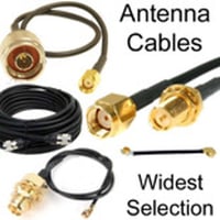
- Cable Type: LMR-400 for long runs; LMR-240 or RG58 for short runs
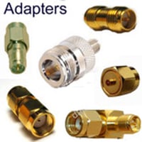
- Connectors: N-Male to SMA-Male or N-Male to TNC-Male depending on device
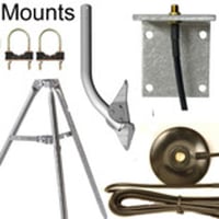
- Mounting: Includes U-bolts for pole mount (1–2" diameter recommended)
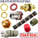
- Weatherproofing: Use coax seal or weatherproof tape on connectors

