


FME to SMA Cables & Adapters
SMA to FME Cables & Adapters
An FME to SMA antenna cable is a coaxial cable assembly that is terminated by a For Mobile Equipment (FME) radio frequency connector at one end and a Sub Miniature version A connector at the other end. They may be used for connection of FME antennas or SMA antennas as well as making connections within and between pieces of cellular and wireless equipment. The connectors used may vary in the combination of gender (for example SMA male to FME male or FME female to SMA female) as required. The connector geometry may also vary with the inclusion of right-angle connectors which provide a reduced footprint, compact mating, and less tension on the attached cable than straight bodied connectors. Pre-assembled cables use a length of high-quality, flexible coax that keeps signal loss to a minimum. Coaxial cable types used include LMR 100, RG 195, and RG 58. The combination of coaxial cable and connectors in these cables is therefore advantageous for installation in enclosed environments where the cable has to be routed for installation.
The physical features of the FME connector in particular are specifically designed for this task as we discuss further on.
FME to SMA adapters
FME to SMA adapters are radio frequency connector adapters that facilitate mating between FME and SMA connectors. They are:
- Between-series, meaning that these adapters make a connection between two different types of connectors (rather than connectors of the same type but differing genders).
- In-line, the adapter unit is straight at both connecting ends.
FME to SMA adapter are impedance matched and fabricated to provide a physical and electrical connection that will not create discontinuities in your radio frequency circuit. They increase interconnectivity between antennas, cables, and radio frequency devices that use either the SMA connector or FME connector. With an FME to SMA adapter, the utility and flexibility of antenna and networking installations are increased across the main application of the key classes of connectors. These 50-Ohm adapters are mated to the SMA connector at one end and the FME connector by screw-coupling as with the regular connectors.
The FME connector
FME connectors are also known as SAP or nipple connectors. These miniature connectors were developed for mobile applications, like vehicles or portable devices where they will potentially encounter jolts, impacts, and vibrations that could cause disengagement or damage to the connection of radio frequency circuit components. It is united for its small and compact dimensions that, when coupled with small diameter flexible coax, allows easy routing within channels and spaces.
Physical specifications of the FME connector
FME connectors are threaded connectors with threading that has threading has an 8mm (M8) by 0.75 mm pitch. The male and female connectors mate by screw-coupling and are rated for over 500 mating cycles.
- The male FME connector is a barrel-shaped connector with threading that is internalized. It is made from machined brass that is nickel plated. It carries a hex nut that may assist in tightening the connector. Within the connector, the male pin is made from gold-plated brass and sits with a recessed Delrin insulator.
- The female FME connector is also made from nickel-plated machined brass and has a diameter of 0.276 inches (7 millimeters). The marked protrusion of its Teflon or Delrin dielectric is distinctive and gives the connector its nipple connector name. It carries a receptacle that is made from phosphor bronze.
Electrical specifications of the FME connector
- The FME connector has an impedance of 50 Ohms.
- The maximum frequency of the FME connector is 2000 MHz (2 GHz).
- The Voltage Standing Wave Ratio (VSWR) is 1.3.
- The working voltage is 500 V.
The SMA connector
Description
This widely used miniature, semi-precision threaded connector is reputed for its performance at microwave frequencies and particularly in cellular and wireless networking applications. It supports reliable broadband performance with low reflection. The SMA connector was developed in the late 1950s and is still manufactured to its military specifications (MIL-STD-348). It mates by screw-coupling to provide a stable, weatherproof connection that is resilient against vibrational forces. For best results, it should be precision tightened by a wrench a the hex nut on the male connector. It is hardwearing and rated for over 500 mating cycles.
Physical specifications of the SMA antenna connector
SMA connectors consist of a quarter-inch (6.35 millimeter) diameter barrel with 36 threads per inch threading. SMA connectors are usually made from machined brass or stainless steel.
- The male SMA connector has internalized threading and a 5/16 inch hex nut for tightening the connector. Within the connector is a brass or copper pin that is surrounded by a PTFE (Teflon) insulator.
- The female SMA connector has externalized threads and an internal receptacle that is surrounded by a Teflon dielectric.
Depending on the manufacturer, the SMA connector may carry a silicone rubber gasket to enhance its weatherproofing.
Electrical specifications of the SMA antenna connector
- Frequency range: from DC to up to 18 GHz depending on the manufacturer
- Impedance: 50 Ohms.
- Voltage rating: peak voltage of up to 500 volts.
- Voltage Standing Wave Ratio: 1.15 + 0.1f
- Radio frequency leakage: -90dB per minute (between 2 and 3 GHz).
RoHS and Conflict Minerals legislation compliant cables and adapters
Our range of FME to SMA coaxial cables and FME to SMA adapters are Restriction of Hazardous Substances (RoHS) compliant. It is also manufactured and distributed in compliance with Section 1502 of the Dodd-Frank Act and the 2021 Conflict Minerals Regulation.
Why are FME to SMA cables and adapters important?
SME and FME radio frequency connectors, cables, and adapters are critical components in broadcast, microwave, wireless networking, land-mobile, and cellular infrastructure and can are used in indoor and outdoor deployments where high performance is required. Cellular networking components need to be reliable, cost-effective, and offer straightforward installation. FME to SMA cables and adapters are routinely used for cell-based mobile communications as they are capable of operating across the wide range of frequency bands and mobile standards (2G, 3G, LTE/4G, and 5G ) required. These cables are desirable for inclusion both in the development of new cell sites and upgrades of existing ones as their flexibility is advantageous for retrofitting as techniques and technologies change. The emergence of metro cell sites, smaller, lower-power, discretely zoned cell sites designed to enhance coverage in urban areas, has necessitated the use of smaller-scale components and cabling which can be connected reliably and efficiently using the FME connector.
FME to SMA cables and adapters for cellular networking
The key base station, antenna systems, and cellular networking components where FME to SMA adapters and cables are used include:
- Base station antennas. The antennas that are arrayed in a base station will span a range of patterns, gains, footprints, and tilt types across all cellular bands. High-quality SMA to FME cables and adapters are used to connect antennas, improving network capacity and performance. These SMA to FME cables have high flexibility and low attenuation and reduce the likelihood of cable faults due to improper routing and connection. This can support densification strategies and new spectrum adds, improve efficiency, and minimize passive intermodulation (PIM), a common problem that can impair cell sensitivity and even block calls.
- Diplexers are passive radio frequency devices that divide the total available bandwidth for cellular networking into non-overlapping frequency bands. This technique is known as frequency division multiplexing (FDM) and is used in CDMA, as well as Frequency Division Duplex (FDD) and Time Division Duplex (TDD), used in LTE networking. This enables a common communications channel to be utilized by different networks or devices. The output of the diplexer is via frequency-selective ports, that often use SMA connectors as an outlet.
- Triplexers are multiplexing devices that are similar to the diplexer described above. Triplexers have three ports that multiplex onto a single port, whereas diplexers multiplex two ports onto a single port. For optimum performance of these devices, a high-quality FME to SMA cable can be critical.
- Feeders, jumpers, or transmission lines are a key application of double-shielded SMA to FME cable due to the physical and electrical properties described above. The use of LMR 100 enhances flexibility, with low-loss performance and RG 195 is a high-strength alternative. Between-series, inline SMA to FME adapters enable FME cables, which have favorable routing and performance, to be used throughout the cellular network, from base transceiver stations to cellular network signal boosters.
SMA to FME cables and adapters for Distributed Antenna Systems (DAS)
Distributed antenna systems is a contemporary strategy for delivering cellular network connectivity in environments where there is limited coverage from a centralized cell tower, for example, indoor environments, tunnels, or expansive public venues like shopping malls or stadia. DAS creates a mesh-network-like arrangement of antennas that are spatially separated over an area to provide enhanced coverage and capacity for cellular networking. The distributed antennas are connected to a central base station for backhaul to the core network. DAS may be driven either by small cell sites or base transceiver stations (BTS) depending on the capacity and performance required.
Deployed DAS nodes are designed to be compact and discrete necessitating the use of subminiature and miniature connector types like SMA and FME. With discrete recessed installations, flexible coax proves vital for completing competent installations. The FME to SMA coax delivers cabling that can be rapidly deployed and securely installed for use with multiple mobile technologies.
DAS systems are diverse with no one single type of system or technology used to set up this cellular networking arrangement. DAS networks can provide cellular coverage as well as wireless local area networking (WiFi and WiMax), depending on their configuration and the types of antennas used. FME to SMA adapters and cables may be used with any of the key components of a DAS to distribute radio frequency signal, including:
- A master unit is the connection point and exchange for bi-directional communication with an outside larger standalone cell site.
- DAS remotes are cellular devices that receive network traffic from the master unit and relay it onward to networked antennas and sends data from the antennas to the master unit.
- DAS antennas distribute the cellular network signal to provide coverage for users. Traffic is relayed to the DAS remote components for forwarding to the master unit.
Frequently asked questions
What is Passive InterModulation (PIM) in cellular networks?
PIM is a type of interference that can affect high-frequency and high--power radio communication. It is a significant problem in cellular communications. Unwanted signals and disturbances generated impair the proper transmission of the cellular signal leading to signal loss, poor call quality, and dropped calls. Causative factors include external interference and how cables, connectors, and radio components are handled. The design and fabrication of radio frequency connectors and cables used in cellular networks are increasingly recognized as having the potential to introduce PIM into a system and cause signal degradation. Transmission lines with poor shielding, due to design or damage, may facilitate the escape of radiofrequency energy and cause noise within the system with derangement of Signal to Noise Ratio (SNR) and generation of odd harmonics and reflections. Because so many cable and connector components are deployed as part of cellular networking installation this interference is almost inevitable to some extent.
The choice of cable assembly used in cellular networking may therefore have a significant impact on the level of PIM generated, in particular:
- Contact resistances and the insertion losses of connectors
- The quality of mating of connectors and adapters
- The precision of impedance matching between cable assembly components
- The attenuation of the cable
This means that cable and adapter selection can have a significant impact on the performance of your cellular installation. Our FME to SMA cables and adapters have the highest standards of fabrication using premium materials to ensure that they perform competently.
What is LMR 100?
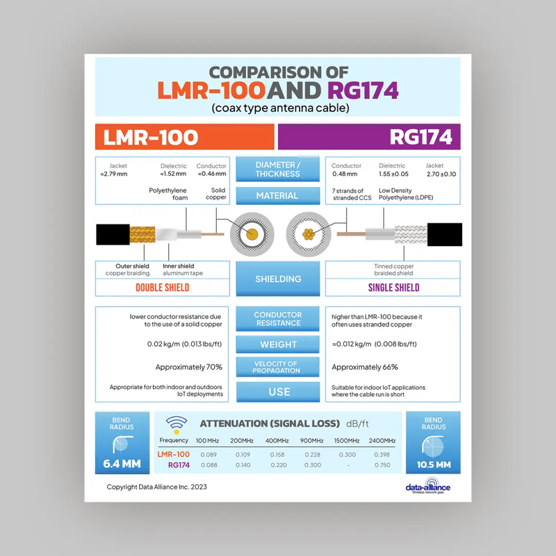
LMR 100 is a type of 50-Ohm coaxial cable that is renowned for its low signal loss and flexibility. Our FME to SMA cable assemblies use a replica of this proprietary coaxial cable, manufactured to identical physical and electrical specifications due to its superior performance.
It has an overall diameter of 0.065 inches (1.6 millimeters), making it an ideal partner for both the SMA and FME connectors. It is comprised of a solid bare copper clad steel inner conductor, a flexible polyethylene dielectric, an aluminum tape outer shield which is covered with a tinned copper braid. The entire coaxial cable is covered in flexible plastic which provides good weather resistance. The double shielding of this cable makes this cable extremely low loss with attenuation rates that are not bettered by alternatives like RG 174. It is also highly flexible with a bend radius of just 0.25 inches (6.24 millimeters), meaning that it can be routed with confidence. With a frequency limit of 63 GHz and robust power handling, LMR 100 is more than adequate for the demands of cellular networking and other common applications of this cable assembly.
What is RG 195 coax?
Where more robust coaxial cable is required, RG 195 provides additional ruggedness while retaining flexibility in FME to SMA cable assemblies. This 50-Ohm coaxial cable has an outer diameter of 0.145 inches (3.63 millimeters) and is composed of a silver-coated copper-clad steel conductor, solid Teflon insulator, braided silver-coated copper shielding, and a flexible Teflon jacket. Its frequency range is more limited, with a maximum frequency of 1 GHz, which is adequate for most cellular frequencies. Despite its larger diameter, it has a bend radius of 0.59 inches (15 millimeters), making it a good option for retrofitting projects.
What is RG 58 coax?
RG 58 is a widely used 50-Ohm coaxial cable that has a diameter of 0.194 inches (4.95 millimeters). It is also flexible and has a minimum bend radius of 0.98 inches (24.89 millimeters). It can be used to support frequencies up to 5 GHz. Its flexibility comes from its stranded center conductor, made from tinned copper. The center conductor is surrounded by a polyethylene dielectric and a single layer of tinned copper braid shielding. The shielding coverage is typically between 70 and 90 percent, depending on the manufacturer. The weatherproof outer PVC jacket makes RG 58 suitable for both indoor and outdoor installation.
In conclusion
FME to SMA cables and adapters are advantageous radio frequency components for cellular and wireless networking. The size, robust connection, and flexibility of these cable assemblies and adapters make them ideal for supporting connectivity in compact spaces. Also, these cables may also be advantageous in a marine setting due to the ease with which routing can take place.
LEARN MORE: